Non-aqueous electrolytic secondary cell
An electrolyte and battery technology, applied in secondary batteries, battery pack components, circuits, etc., can solve the problems of deterioration of charge-discharge performance and uneven distance
- Summary
- Abstract
- Description
- Claims
- Application Information
AI Technical Summary
Problems solved by technology
Method used
Image
Examples
no. 1 example
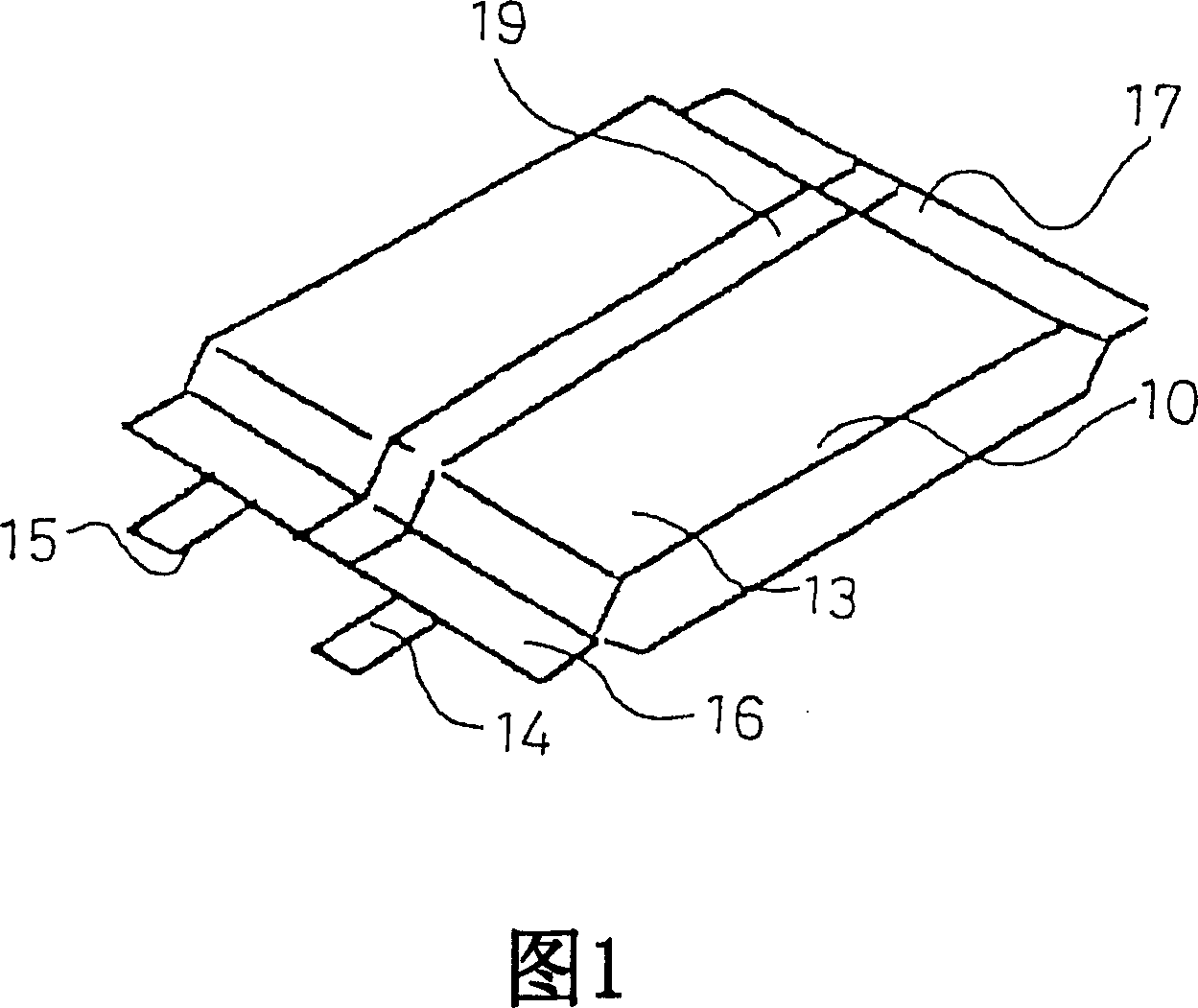
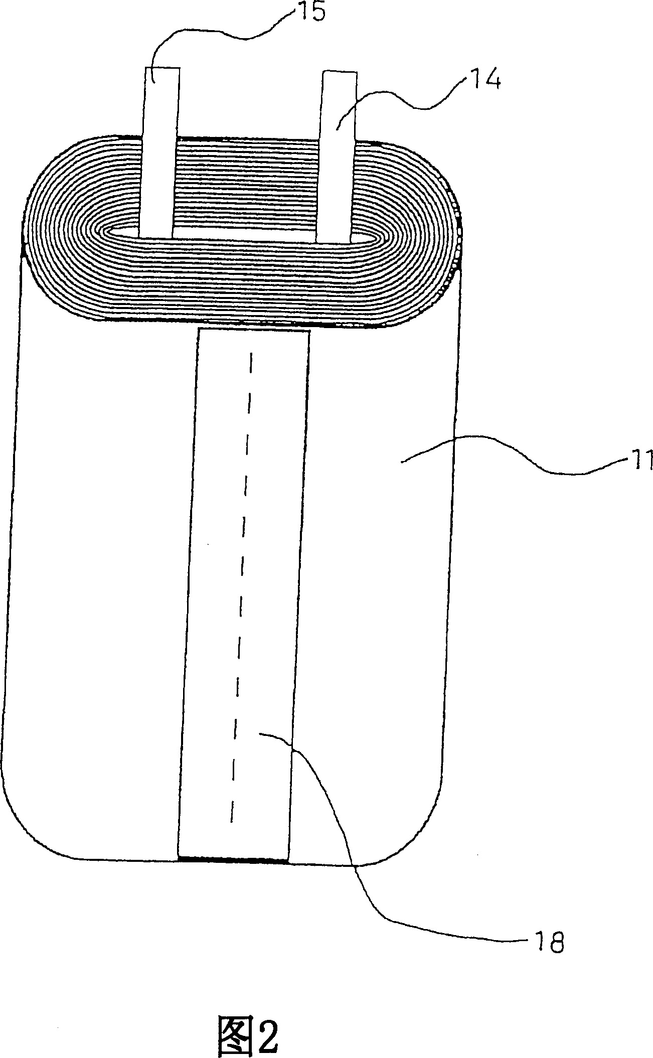
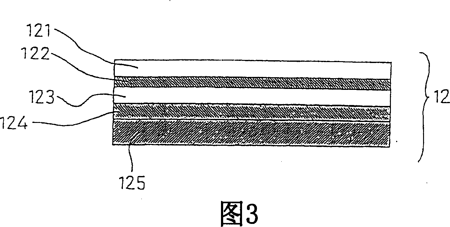
[0071] Hereinafter, a first embodiment encompassed by the present invention will be described with reference to FIGS. 1-3.
[0072] The nonaqueous secondary electrolyte battery 10 according to the present embodiment includes an electrode body 11 (see FIG. 2 ) consisting of a positive electrode plate, a negative electrode plate, and a separator housed in a battery case 13 composed of a resin plate 12 (see FIG. 3 ). A material (not shown) is formed together with a non-aqueous electrolyte (not shown). Parameter 14 represents the positive terminal, and parameter 15 represents the negative terminal. Parameter 16 indicates the edge to be welded on the end of the battery case on which the illustrated portion of the terminal 14, 15 is placed. Parameter 17 indicates the edge to be welded on the end of the battery case opposite edge 16 .
[0073] The resin board 12 is an aluminum-resin board. As shown in FIG. 3 , the resin plate 12 includes, in descending order, a PET layer 121 with ...
no. 2 example
[0093] The nonaqueous secondary electrolyte battery according to the present embodiment includes an elliptical wound power generating element consisting of a positive electrode plate housed in a pouch-shaped battery case formed by a hot-melt metal laminated resin film, a separator material, and a negative electrode plate with a non-aqueous electrode plate. A water electrolyte (not shown) is formed together. The appearance of this nonaqueous secondary electrolyte battery is shown in FIG. 4 . A reference number 20 denotes a pouch-shaped battery case, and a reference number 21 denotes a power generating element including a positive electrode plate and a negative electrode plate wound elliptically by a polyethylene microporous film (separator) as a separator. Parameter 22 represents the winding shaft of the generating element, parameter 23 represents the positive lead end connected to the positive plate, and parameter 24 represents the negative lead end connected to the negative p...
no. 3 example
[0116] This embodiment differs from the above-described second embodiment only in the structure of the electrolytic solution and the welded portion. Other structures of this embodiment are the same as those of the second embodiment shown in Figs. 4-6. As for the battery of the third embodiment, the following six batteries 3A-3F were prepared. As for the electrolyte solution, these batteries use a 6 A 3:8 (by volume) mixture of ethylene carbonate and diethyl carbonate.
[0117] battery 3A
[0118] The structure of the welded part is shown in Figure 8. The thickness Y of the inner end of the welded portion was 300 μm, and the thickness X of the outer end of the welded portion was 250 μm.
[0119] Battery 3B
[0120] The structure of the welded part is shown in Figure 8. The thickness Y of the inner end of the welded portion was 300 μm, and the thickness X of the outer end of the welded portion was 200 μm.
[0121] Battery 3C
[0122] The structure of the welded part is s...
PUM
| Property | Measurement | Unit |
|---|---|---|
| radius | aaaaa | aaaaa |
| thickness | aaaaa | aaaaa |
| thickness | aaaaa | aaaaa |
Abstract
Description
Claims
Application Information
 - R&D
- Intellectual Property
- Life Sciences
- Materials
- Tech Scout
- Unparalleled Data Quality
- Higher Quality Content
- 60% Fewer Hallucinations
Browse by: Latest US Patents, China's latest patents, Technical Efficacy Thesaurus, Application Domain, Technology Topic, Popular Technical Reports.
© 2025 PatSnap. All rights reserved.Legal|Privacy policy|Modern Slavery Act Transparency Statement|Sitemap|About US| Contact US: help@patsnap.com


