Linear motor and method of producing linear motor

A linear motor and structure technology, applied in the manufacture of motor generators, stator/rotor bodies, electrical components, etc., can solve the problems of magnet manufacturing cost increase, increase in number of parts, cost increase, etc., achieve reliable assembly and reduce parts Number, effect of reliable assembly

Inactive Publication Date: 2007-05-23
KONICA MINOLTA MEDICAL & GRAPHICS INC
View PDF1 Cites 0 Cited by
  • Summary
  • Abstract
  • Description
  • Claims
  • Application Information

AI Technical Summary

Problems solved by technology

[0005] Conventional linear motors are expensive because they use cylindrical magnets. In other words, to make magnets into cylinders, through-holes must be opened, which increases the manufacturing cost of magnets.
In addition, since a plurality of magnets must be arranged in the direction of mutual repulsion, a central axis is used, which increases the number of parts and increases the cost.

Method used


Image

  • Linear motor and method of producing linear motor
  • Linear motor and method of producing linear motor
  • Linear motor and method of producing linear motor

Examples


Embodiment Construction

[0063] Hereinafter, although embodiment of the linear motor and the manufacturing method of the linear motor of this invention is demonstrated, this invention is not limited to this embodiment. In addition, although embodiment of this invention shows the most preferable embodiment of invention, this invention is not limited to this.

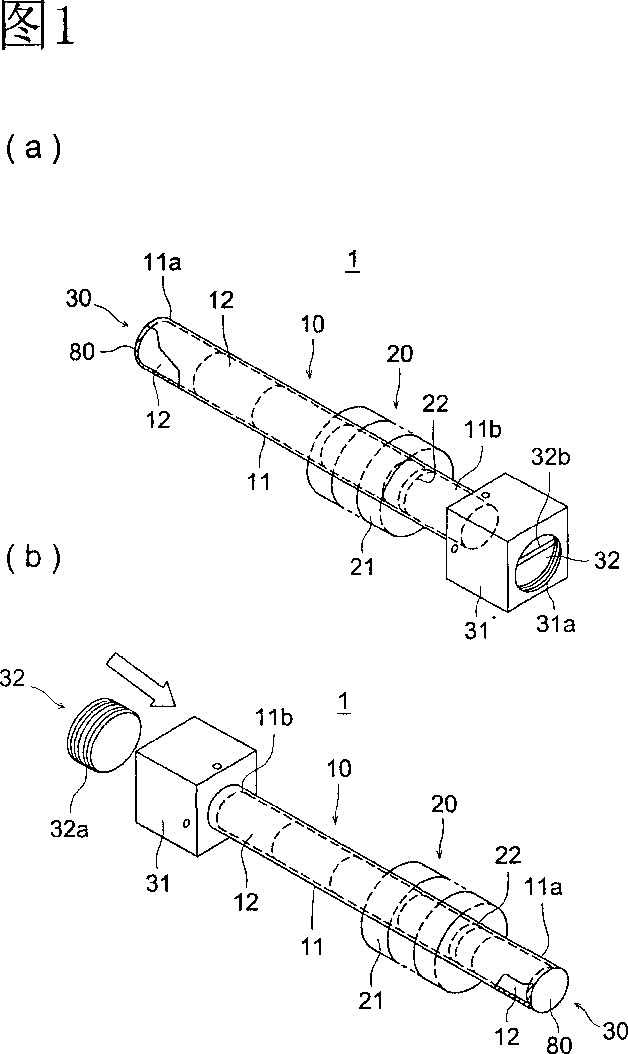
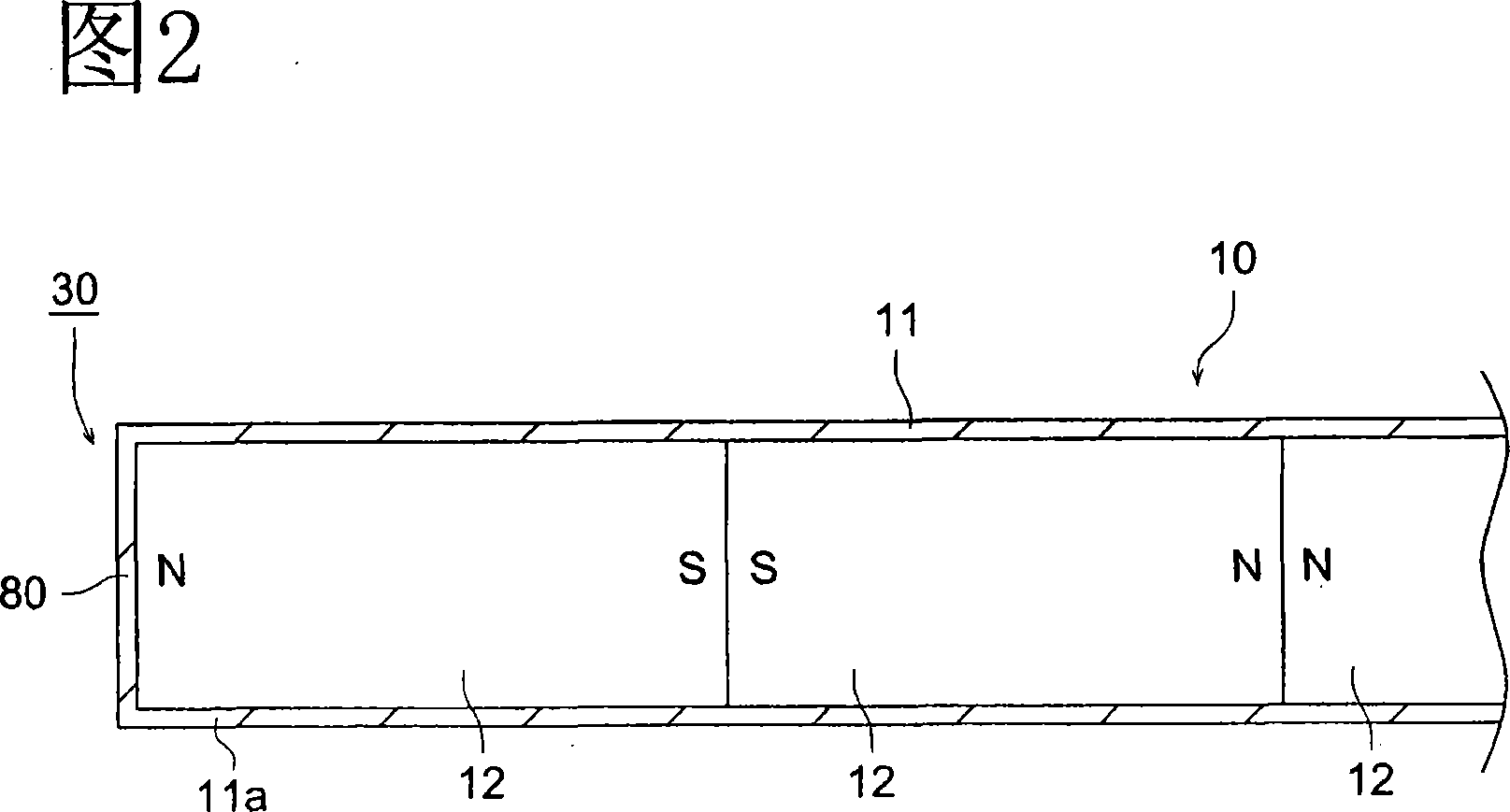
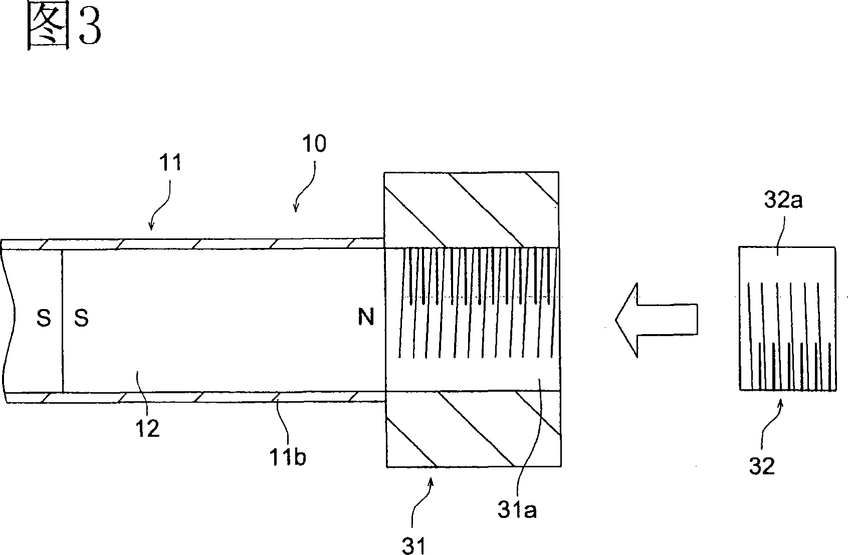
[0064] FIG. 1 is a schematic diagram of a linear motor, FIG. 2 is a sectional view of an essential part of one end of the linear motor, and FIG. 3 is a sectional view of an essential part of the other end of the linear motor.

[0065] The linear motor 1 of this embodiment is comprised of the stator 10 fixed to the support member which is not shown in figure, and the movable member 20 which linearly moves along the outer peripheral surface of the stator 10. As shown in FIG.

[0066] The stator 10 is composed of a duct-shaped member 11 and a plurality of magnets 12 accommodated in the duct-shaped member 11 . The plurality of magnets 12 arranged in...


PUM

PropertyMeasurementUnit
thicknessaaaaaaaaaa

Abstract

A linear motor (1) having a pipe-like member (11), a stator (10) in which magnets (12) are received and serially arranged in the pipe-like member (11) such that the same polarity of adjacent magnets (12) faces each other, and a mover (20) movable and provided so as to face the outer peripheral surface of the pipe-like member (11). The pipe-like member (11) has at its one end section (11a) a come-out stop mechanism (30) for restricting the magnets (12) from coming out from inside the pipe-like member (11). The magnets can be simply and reliably installed in the pipe-like member so as not to come out and rattle.

Description

technical field [0001] The present invention relates to a linear motor, and more particularly, to a linear motor comprising a stator in which a plurality of magnets are arranged in parallel, and a mover capable of movement arranged to face the outer peripheral surface of the stator, and a method for manufacturing the linear motor . Background technique [0002] For example, linear motors are proposed for parts that require linear movement accuracy, such as print heads and exposure scanners in OA equipment, and exposure scanners in medical equipment. [0003] Among them, the rotary shaft type linear motor represented in JP-A-10-313566 is suitable for precise conveyance of OA equipment in terms of speed performance and space saving compared with conventional linear motors using flat magnets. However, as shown in FIG. 18 , a cylindrical magnet 100 having a through hole in the center is used, and a central axis 101 is used to store the cylindrical magnet 100 closely adjacent to...

Claims


Application Information

Patent Timeline
Patent Type & Authority Applications(China)
IPC IPC(8): H02K41/03H02K15/03
CPCH02K15/03H02K41/03Y10T29/49009
Inventor 野泽肇成田孝之
Owner KONICA MINOLTA MEDICAL & GRAPHICS INC
Why Eureka
Try Eureka