Photogravure roller

A technology of gravure printing and gravure printing machine, applied in the direction of gravure rotary printing machine, printing, printing machine, etc., can solve the problems of printing slurry flow limitation, coating slurry thickness variation, rough coating slurry film, etc.

Active Publication Date: 2007-06-06
MURATA MFG CO LTD
View PDF0 Cites 9 Cited by
  • Summary
  • Abstract
  • Description
  • Claims
  • Application Information

AI Technical Summary

Problems solved by technology

[0008] However, according to the technology described in Patent Document 2, since the gap of each cut is smaller than the width of each mesh wall, when using a printing paste having a relatively high viscosity (such as a conductive paste), the printing paste will be separated from adjacent meshes. The flow between them is restricted, so the film printed with paste often has traces of grids, that is, a rough paste film is formed.
[0009] Furthermore, according to the technique described in Patent Document 2, since the walls defining the plurality of grids formed in the image area are arranged to extend in a direction at an angle to the printing direction, when the substrate is separated from the gravure printing cylinder , at a certain angle on the circumference of the gravure printing cylinder, the so-called tendrils of printing paste will be produced, resulting in local unevenness in the peripheral part of the printing paste film
Irregularities in tendril orientation lead to overlapping which further leads to variations in size film thickness

Method used


Image

  • Photogravure roller
  • Photogravure roller
  • Photogravure roller

Examples


Embodiment Construction

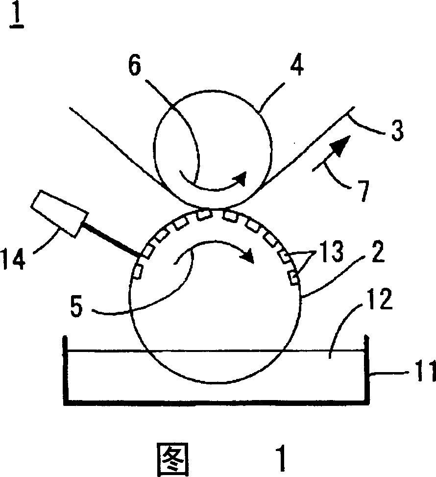
[0039] Fig. 1 is a schematic front view of a gravure printing machine according to a first embodiment of the present invention.

[0040] The gravure printing machine 1 includes a gravure printing cylinder 2 and an impression cylinder 4 that faces the gravure printing cylinder 2 and holds a printing substrate 3 therebetween. The printing cylinder 2 and the impression cylinder 4 rotate in the directions of arrows 5 , 6 , respectively, so that the printing substrate 3 is transported in the direction of arrow 7 .

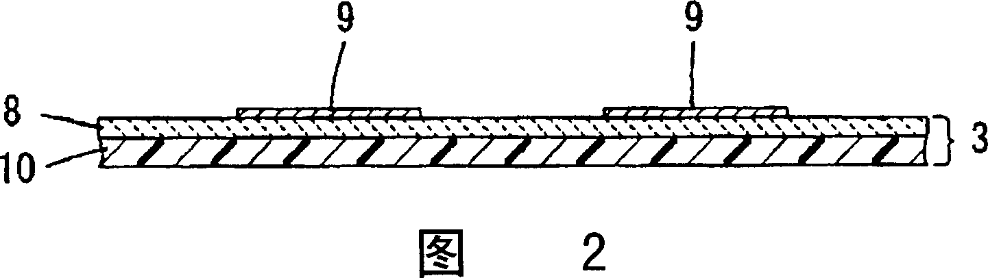
[0041] The gravure printing machine 1 is used to manufacture multilayer ceramic electronic components such as multilayer ceramic capacitors. More specifically, the gravure printing machine 1 is used to form a paste film on a printed substrate 3 by gravure printing as a wiring pattern layer defining a part of a laminated board in a multilayer ceramic electronic component. More specifically, as shown in FIG. 2 , conductive paste films 9 constituting internal electrodes of ...


PUM


Abstract

Disclosed is a gravure rolling drum of the photogravure printing press capable of forming a coating membrane on the substrate using photogravure by the printing press. The gravure rolling drum is provided with: an image area forming on the circumferential surface of the gravure rolling drum on which the coating pulp forms a coating membrane, and printing-direction walls substantially extending in printing-direction and perpendicular walls extending substantially in direction perpendicular to the printing-direction walls formed in the image areas, and a plurality of cells defined by the printing-direction walls and substantially perpendicular walls. Each perpendicular wall has a cut opening formed therein to communicate the adjacent cells.

Description

[0001] The patent application of the present invention is a divisional application of the invention patent application with the application number "200410035048.2" submitted by the applicant on April 19, 2004, and the invention title is "Intaglio printing machine and method for manufacturing multilayer ceramic electronic components". technical field [0002] The present invention relates to a gravure printing machine for manufacturing multilayer ceramic electronic components and a method for manufacturing multilayer electronic ceramic electronic components using the gravure printing machine. The present invention particularly relates to a technology for improving the smoothness of paste films formed by gravure printing. Background technique [0003] In order to manufacture a multilayer ceramic electronic component such as a multilayer ceramic capacitor, a process of forming a conductive paste film as an internal electrode on a ceramic printed circuit board may be performed. T...

Claims


Application Information

Patent Timeline
Patent Type & Authority Applications(China)
IPC IPC(8): B41F13/11B41F9/00B41N3/00B41M1/10H01G4/30H05K1/09H05K3/12
CPCH05K1/092H05K3/12B41F13/11H01G4/308H05K3/4629
Inventor 桥本宪高岛浩嘉金山吉广田畑和宽西泽孝广
Owner MURATA MFG CO LTD
Why Eureka
Try Eureka