Supercharge Your Innovation With Domain-Expert AI Agents!

Heating-power expansion valve

A technology of thermal expansion valve and valve body, applied in the field of thermal expansion valve, can solve the problems of insufficient welding reliability, difficult welding state, insufficient welding strength, etc., and achieve the effects of avoiding poor welding, avoiding insufficient strength, and ensuring insufficient strength

Active Publication Date: 2007-06-13
ZHEJIANG SANHUA AUTOMOTIVE COMPONENTS
View PDF2 Cites 6 Cited by
  • Summary
  • Abstract
  • Description
  • Claims
  • Application Information

AI Technical Summary

Problems solved by technology

[0008] In the conventional thermal expansion valve, in order to form the welded cone surface, the head is formed with a protrusion and a cone shape, and the hole in the outer wall is inclined downward toward the center to form a peripheral part. The processing process is complicated.
[0009] The thermal expansion valve scheme of secondary welding is adopted, and the projection welding is welded along the whole circumference of the spherical surface, which may cause insufficient welding strength
[0010] Moreover, in the previous thermal expansion valve, there may be welding between the hole on the outer wall and the head, and it is difficult to achieve a stable welding state.
[0011] In addition, in the previous thermal expansion valve, when the outer wall hole and the head were welded, there was a possibility that the welding reliability was not sufficient
[0012] In addition, when the spherical head is obliquely welded, the contact with the hole is uneven, and poor welding may occur

Method used


Image

  • Heating-power expansion valve
  • Heating-power expansion valve
  • Heating-power expansion valve

Examples


Embodiment 1

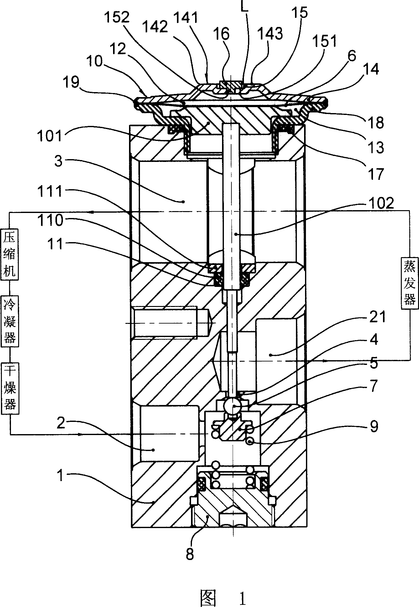
[0041] FIG. 1 depicts a thermal expansion valve installed in a refrigeration cycle in a vehicle air conditioner or the like. The valve body 1 is provided with a high-pressure refrigerant flow path 2 through which the liquid refrigerant flowing into the evaporator flows and a low-pressure refrigerant flow path 3 flowing out from the evaporator. There is a valve hole formed by a small-diameter orifice in the middle of the high-pressure refrigerant flow path 2. 4. Therefore, the liquid refrigerant flowing from the accumulator (not shown) into the high-pressure refrigerant flow path 2 passes through the valve hole 4 with a relatively small flow path area and expands adiabatically, and flows into the passage 21 . The opening portion of the valve hole 4 on the refrigerant inflow side forms a valve seat, and the opening degree of the valve hole 4 is changed by approaching or separating the spherical valve element member 5 at the valve seat. The valve core part 5 is supported by the ...

Embodiment 2

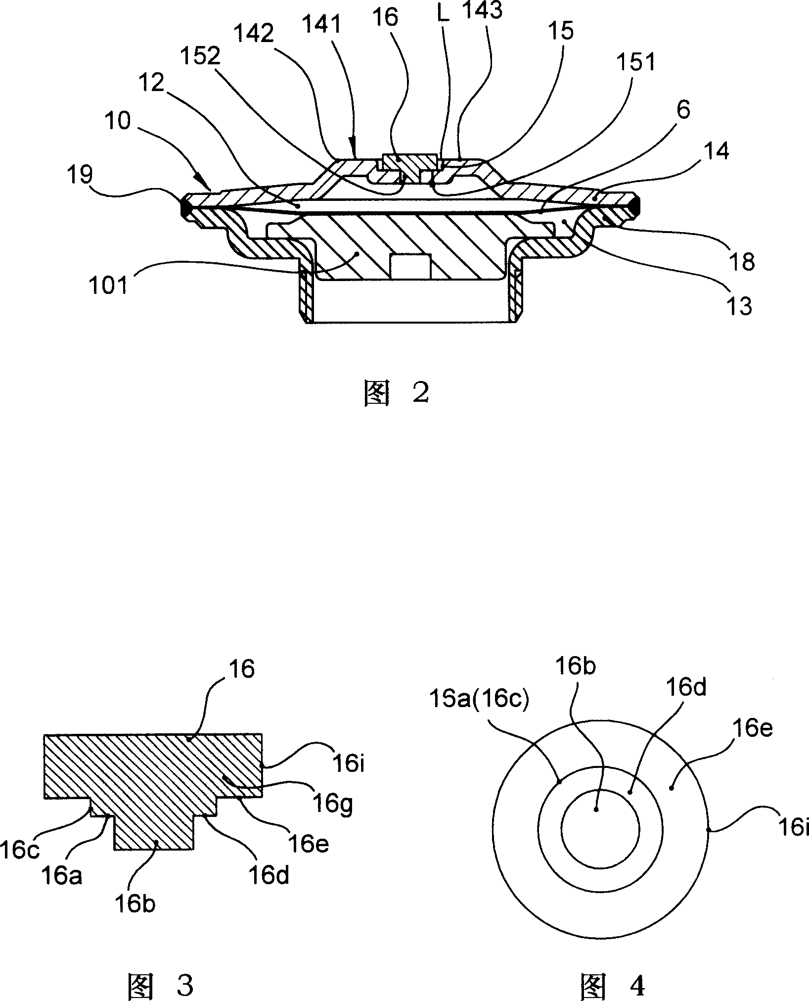
[0055] As shown in FIG. 5, a disc-shaped sealing head is provided with a protrusion 16a on its lower surface 16e, and the protrusion 16a is located around a convex portion 16b formed integrally at the central part of the surface 16e of the sealing head 16, as The edge portion 6f is integrally arranged with the head. The convex part 16b and the protruding part 16a may form a separate body from the above-mentioned head.

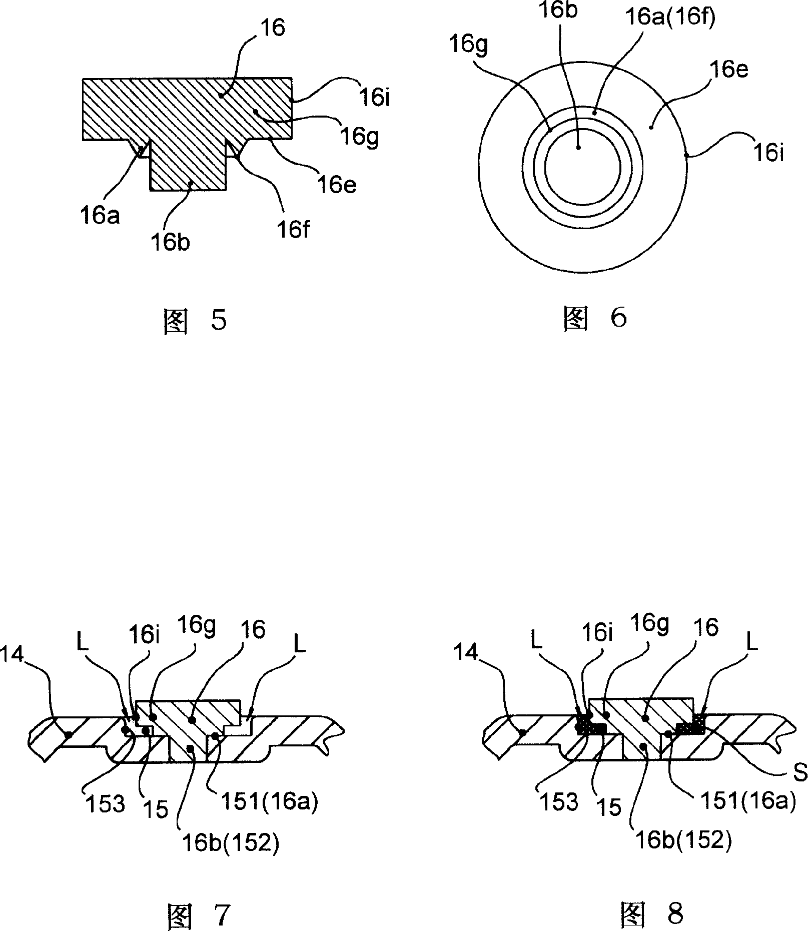
[0056] According to the above-mentioned head 16, the convex portion 16b of the head 16 is inserted into the hole formed on the bottom 151 of the recess 15 of the outer wall 14. In order to arrange the head 16 in the recess 15 and play a guiding role, the above-mentioned flange The front end of 6f is in contact with the bottom of the recess 15 of the outer wall 14 , and the head 16 is combined with the outer wall 14 . Therefore, the cap 16 can be stably and firmly combined with the outer wall 14 . As a result, during the resistance welding of the two, the ener...


PUM


Abstract

The invention relates to thermostatic expansion valve. It includes one air box head set on the valve body to control secondary refrigerant flow rate. The air box head has sealed chamber formed by diaphragm and outer wall, realize sealing by filling into secondary refrigerant from the hole. Its features are that the hole is set at the bottom of out wall cove; end plate is discoid and set jut which is connected with the bottom to seal the hole by electric resistance welding; cove inner clearance is formed around the end plate. The end plate of the invention is set clearance and connected with the cove of the air box head out wall which can process welding between them without electrical on-state. Thus it can prevent poor bonding, proof strength under-capacity.

Description

technical field [0001] The invention relates to a thermal expansion valve, in particular to a thermal expansion valve used in a vehicle air-conditioning and refrigeration system. Background technique [0002] There are many types of thermal expansion valves used in refrigeration cycles, such as JP-Ping 8-226567 bulletin. This thermal expansion valve includes the following: the high-pressure refrigerant passage for the refrigerant to flow into the evaporator and the low-pressure refrigerant passage for the refrigerant to flow out of the evaporator, A valve body with a valve hole in the middle of the above-mentioned high-pressure refrigerant flow path, a valve core part that changes the opening of the valve hole by touching or leaving the valve hole of the valve body, and a drive rod to drive the valve to control the movement of the valve body. The diaphragm of the core part, the airtight chamber filled with the temperature-sensitive gas isolated by the ...

Claims


Application Information

Patent Timeline
IPC IPC(8): F16K1/14F16K31/68F25B41/06
CPCF25B2341/0683
Inventor 裘浩明杜又德尹斌小池隆志
Owner ZHEJIANG SANHUA AUTOMOTIVE COMPONENTS
Features
  • R&D
  • Intellectual Property
  • Life Sciences
  • Materials
  • Tech Scout
  • Unparalleled Data Quality
  • Higher Quality Content
  • 60% Fewer Hallucinations
Learn More