Light-source module and mfg. method

A technology of a light source module and a manufacturing method, which is applied in the direction of cooling/ventilation/heating transformation, discharge lamps, discharge tubes, etc., and can solve problems such as easy deterioration, heat dissipation of the heat dissipation cavity, and temperature rise of the cooling liquid of the heat dissipation cavity.

Inactive Publication Date: 2007-06-13
CHUNGHWA PICTURE TUBES LTD
View PDF0 Cites 0 Cited by
  • Summary
  • Abstract
  • Description
  • Claims
  • Application Information

AI Technical Summary

Problems solved by technology

[0006] However, the zinc phosphate coated on the outer surface of the heat dissipation cavity will produce a black crystal film on the outer surface of the heat dissipation cavity after chemical changes, and these black crystal films will make it difficult for the heat inside the heat dissipation cavity to dissipate , which in turn causes the temperature of the coolant inside the cooling chamber to rise
Once the coolant is at high temperature for a long time, it is easy to deteriorate, which will change the optical properties of the coolant such as refractive index and transmittance, and then affect its service life

Method used


Image

  • Light-source module and mfg. method
  • Light-source module and mfg. method
  • Light-source module and mfg. method

Examples


Embodiment Construction

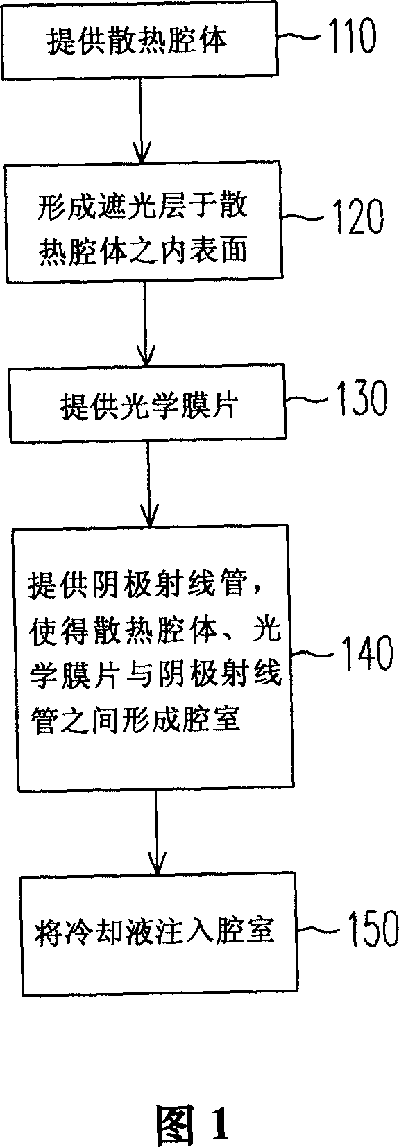
[0045] FIG. 1 is a schematic flowchart of a method for manufacturing a light source module according to a preferred embodiment of the present invention. Please refer to FIG. 1 , the manufacturing method of the light source module is as described in step 110 , providing a heat dissipation cavity with an opening. The material of the cooling chamber is, for example, copper-aluminum alloy, preferably ADC12. Then, as described in step 120 , a light-shielding layer is formed on the inner surface of the heat dissipation cavity, wherein the material of the light-shielding layer is, for example, a dark material. In this embodiment, the method of forming the light-shielding layer is, for example, to firstly provide a material constituting the light-shielding layer, which is, for example, dry powder. In a preferred embodiment, the dry powder is composed of zinc phosphate, for example.

[0046] Based on the above, the dry powder is then adhered to the inner surface of the heat dissipati...


PUM


Abstract

The invention discloses a kind of light source module, which includes cathode ray tubes, heat dispersing cavity, photics film, light filtering layer and cooling fluid. The cathode ray tube has the light emitting end that is used to emit ray. The heat dispersing cavity is connected to the light emitting end of the cathode ray tube, whereas the ray is emitted to the outer of the heat dispersing cavity through the opening of the heat dispersing cavity. The photics film is set at the openings, and makes the cathode ray tubes, heat dispersing cavity and the photics film form a cavity. The light filtering layer is set on the inner surface of the heat dispersing cavity, whereas the cooling fluid is filled in the cavity.

Description

technical field [0001] The invention relates to a light source module of a display and a manufacturing method thereof, in particular to a light source module with a cathode ray tube display device and a manufacturing method thereof. Background technique [0002] In a light source module of a cathode ray tube (cathode ray tube, CRT) display, the cathode ray tube tends to generate considerable heat energy after running for a period of time. For a display using a cathode ray tube as a light-emitting element, if the heat energy is not properly removed, the image output quality will be degraded. Therefore, in a cathode ray tube display, there is usually an appropriate heat dissipation mechanism to remove the heat energy generated by the cathode ray tube. [0003] A known method is to connect the light emitting end of the cathode ray tube to the heat dissipation cavity, and fill the heat dissipation cavity with cooling liquid, and the light emitted by the cathode ray tube is emit...

Claims


Application Information

Patent Timeline
Patent Type & Authority Applications(China)
IPC IPC(8): H01J29/00H01J7/26H01J29/89H05K7/20
Inventor 许士浤吴世民莫启能
Owner CHUNGHWA PICTURE TUBES LTD
Why Eureka
Try Eureka