Arrangement in air-cooled internal combustion engine

An internal combustion engine, air inlet technology, applied in air cooling, combustion air/combustion-air handling, mechanical equipment, etc., can solve the problems of loud sound, adverse effects of operator's working conditions, etc., and achieve the effect of reducing sound

Active Publication Date: 2007-06-13
HUSQVARNA AB
View PDF1 Cites 0 Cited by
  • Summary
  • Abstract
  • Description
  • Claims
  • Application Information

AI Technical Summary

Problems solved by technology

[0006] However, the arrangement described in the patent US-Patent No. 4,841,920 has the disadvantage that it produces a loud sound, which will have an adverse effect on the working conditions of the operator

Method used


Image

  • Arrangement in air-cooled internal combustion engine

Examples


Embodiment Construction

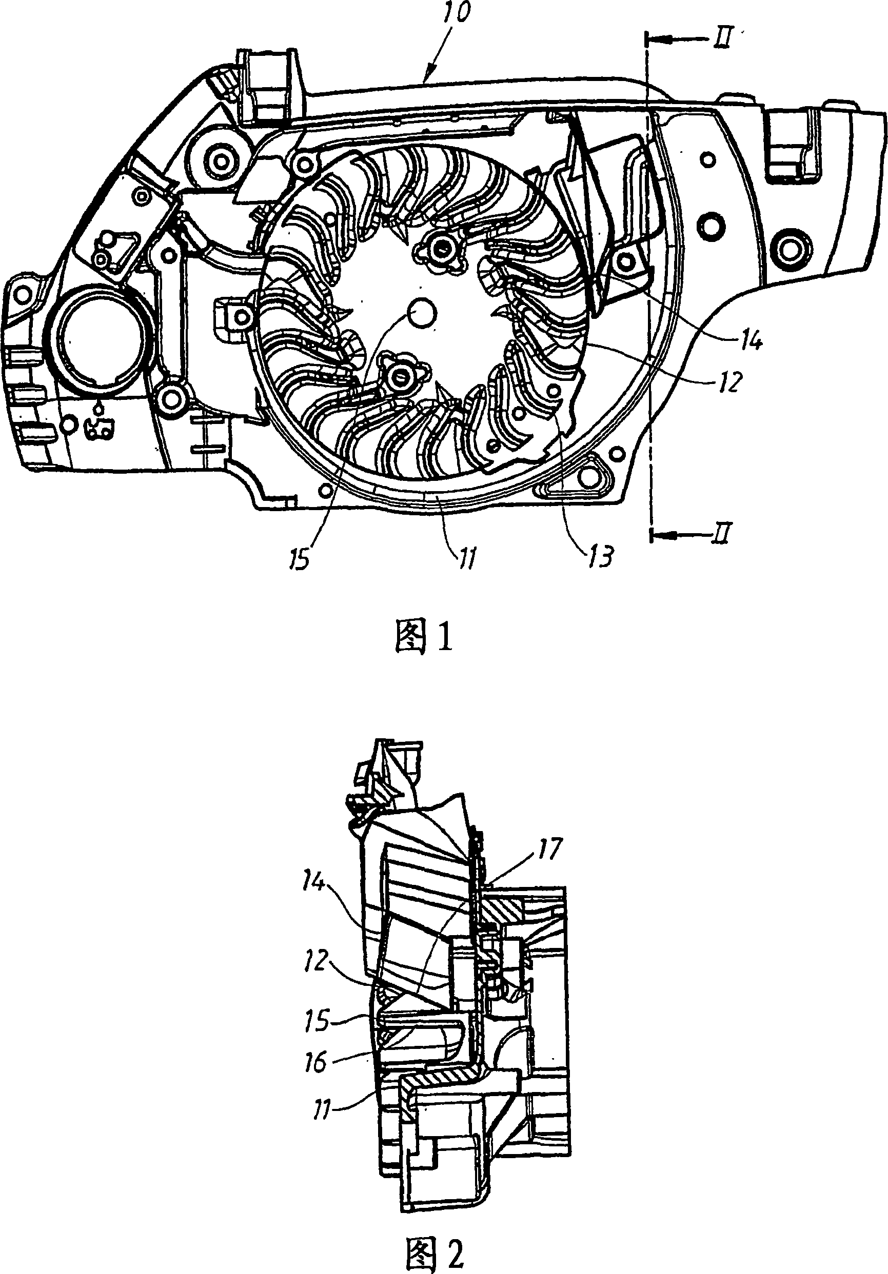
[0016] Figure 1 is a side view of the arrangement of the invention for use in a chainsaw, showing only a section 10 of the chainsaw body. A fan shroud surrounding the arrangement is not shown in the figure. The chain saw segment 10 includes a fan housing 11 and a fan wheel 12 . The fan wheel 12 rotates about an axis 15 and is equipped with vanes 13 . The fins are S-shaped and extend substantially radially of the fan wheel. Each fin 13 has an outer edge 16 substantially parallel to the axis of rotation 15 . The shape and number of fins 13 are selected to meet the specific application requirements of the fan.

[0017] An air inlet 14 is provided near the periphery of the fan wheel 12 . The air inlet 14 is positioned such that the air inlet 14 collects as much air as possible. The majority of the generated air flow turns within the fan housing 11 around the periphery of the fan wheel 12 . The air inlet 14 is therefore arranged such that the air inlet 14 exposes a large area...


PUM


Abstract

Arrangement in an internal combustion engine, said arrangement comprises a fan for supplying combustion air to a carburetor. The fan comprises a fan housing (11) and a fan wheel (12) provided with a number of wings (13) extending in substantially radial direction from the axle (15) of rotation for the fan wheel (12). The arrangement further comprises an air inlet (14) for combustion air to the carburetor arranged at the outer edge of the wings (13) on the fan wheel (12). The outer edge of the wings (13) is arranged in a direction substantially parallel to the axle (15) of rotation for the fan wheel 10 (12). The side of the air inlet (14) closest to the outer edge of the wings (13) on the fan wheel (12) is arranged at an angle of 10 DEG to 60 DEG in relation to the outer edge of the wings (13) on the fan wheel (12) to reduce the amount of sound generated.

Description

technical field [0001] The invention relates to an arrangement in an internal combustion engine. Background technique [0002] Small two-stroke internal combustion engines are used in hand tools such as chainsaws and power cutters. Enabling air from the surroundings to flow through the tool is a frequently employed solution to ensure that the heat generated during combustion within the engine does not damage the engine and to provide fresh air to the carburetor where it mixes with fuel. This air and fuel mixture is then introduced into a combustion chamber within the cylinder. [0003] In order to ensure a constant flow of cooling and combustion air through the tool, the tool is equipped with a fan having a fan housing and a fan wheel. The fan creates an air flow that circulates inside the tool housing so that heat-generating components are cooled. A portion of the air flow from the fan wheel enters an air inlet connected to the carburetor where the air is mixed with fuel...

Claims


Application Information

Patent Timeline
Patent Type & Authority Applications(China)
IPC IPC(8): F02M35/10F02M35/12F02B63/02F01P5/06F02M35/06F01PF01P1/02
CPCF02M35/1017F02M35/10288F02M35/10144F02M35/10019F02M35/06F01P5/06F01P1/02
Inventor D·冈纳森G·兰登
Owner HUSQVARNA AB
Why Eureka
Try Eureka