Vibration earphone

a technology of vibration earphones and earphones, which is applied in the direction of transducer details, earpiece/earphone attachments, electrical transducers, etc., can solve the problem that the diaphragm of the usual earphones is too small to generate sufficient low sound, and achieves low sound vibration, high sound of vibration, and improved sound output from the earphones

Inactive Publication Date: 2012-04-05
ECOSHELL
View PDF11 Cites 9 Cited by
  • Summary
  • Abstract
  • Description
  • Claims
  • Application Information

AI Technical Summary

Benefits of technology

[0016]To overcome the above problems, the present invention provides a vibration earphone which can output high sound vibrations toward the eardrum and simultaneously output low sound (about 40% of whole sound) to the wall of the external auditory through a cylindrical low sound transmitting member, so as to improve the efficiency of sound output from the earphone.
[0020]The vibration earphone of this invention can output high sound of vibrations toward the eardrum, and simultaneously output low sound vibrations to transmit it to the internal ear via skin and bone, through a cylindrical low sound transmitting member housing the vibration member, so as to improve the efficiency of sound output from the earphone and reduce the damage of the eardrum.
[0021]In contrast to the usual earphone which makes user's ear ring due to bumping of the diaphragm, the earphone of this invention can overcome this problem.

Problems solved by technology

However, the conventional osteophony earphone makes the mastoid vibrate only at the center of the earphone to output high frequency range of sound, such that the sound can be heard only around the center of the earphone.
Moreover, the usual earphone generates high sound at the center where the coil is positioned and low sound at the outer side through the diaphragm; however, the diaphragm of the usual earphone is too small to generate sufficient low sound.

Method used


Image

  • Vibration earphone
  • Vibration earphone
  • Vibration earphone

Examples


Embodiment Construction

[0028]Reference will now be made in detail to the present embodiments of the present invention, examples of which are illustrated in the accompanying drawings, wherein like reference numerals refer to the like elements throughout. The embodiments are described below in order to explain the present invention by referring to the figures.

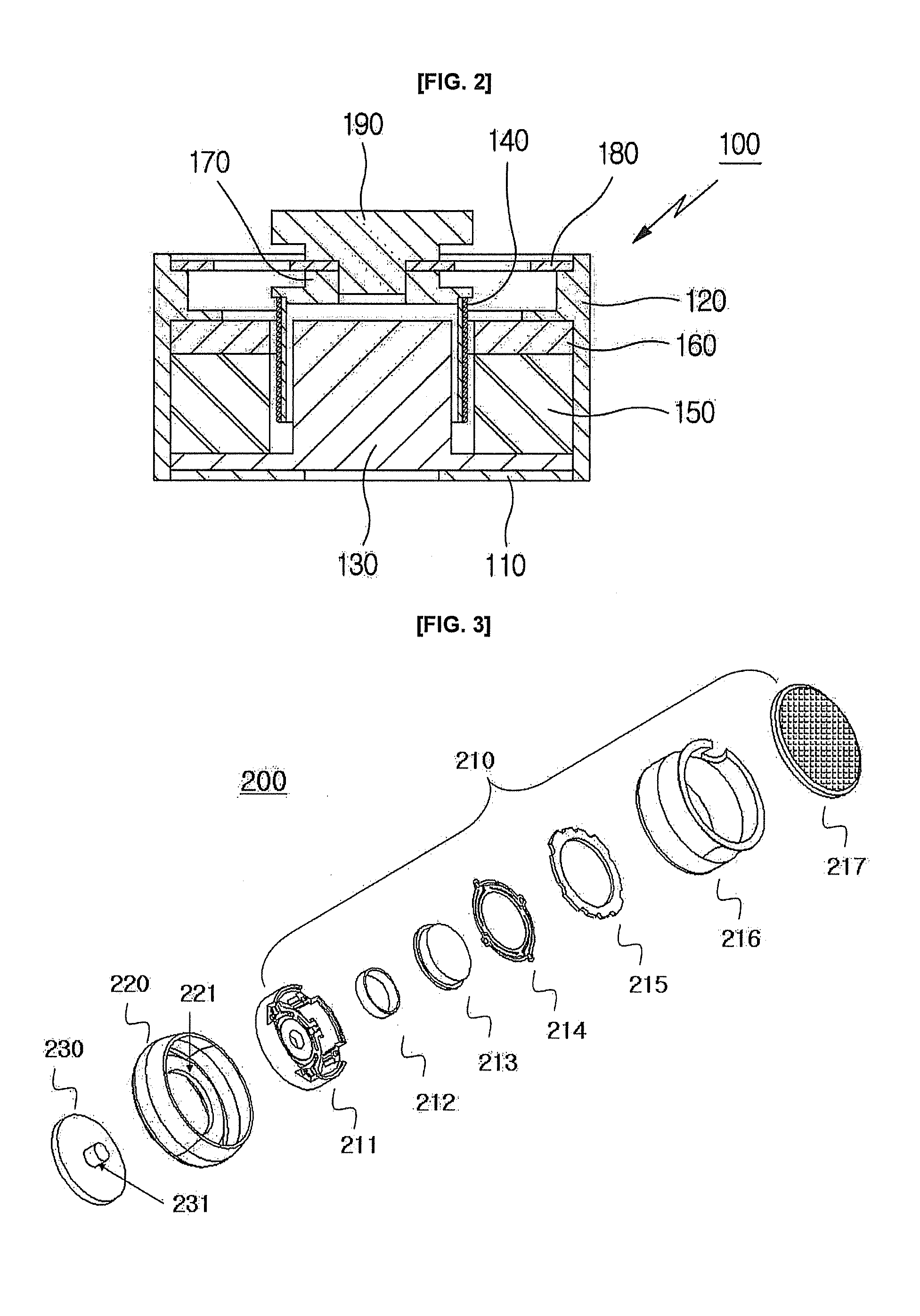
[0029]FIG. 3 is an exploded perspective view illustrating a vibration earphone according to the present invention, and FIG. 4 is a cross sectional view illustrating the assembled vibration earphone according to the present invention.

[0030]Referring to FIGS. 3 and 4, a vibration earphone 200 according to one embodiment of the present invention comprises a vibration member 210, a low sound transmitting member 220 and a mastoid 230.

[0031]Here, the vibration member 210 may be one of the conventional vibrating modules for generating sound, for example, may comprise a face plate 211, a voice coil 212, a basket 213 with magnet coupled thereto, a vibrating fla...


PUM


Abstract

The present invention relates to a vibration earphone that improves the efficiency of sound output from the earphone by outputting vibrations for the high sound frequency range through a mastoid and by simultaneously outputting vibrations for the low frequency range through a cylindrical low sound transmitting member. The vibration earphone comprises a vibration member for outputting sound through vibrations and including a face plate, a voice coil, a basket with a magnet coupled thereto, and a cover; the low sound transmitting member housing the vibration member therein, for outputting vibrations for low sound through an external wall inside an ear; and a mastoid for outputting vibrations for the high sound frequency range generated from the face plate through a projection passing through the low sound transmitting member and inserted in and coupled to a hole defined in a central portion of the face plate of the vibration member.

Description

CROSS-REFERENCE TO RELATED APPLICATIONS[0001]This application is a national phase of PCT International Patent Application No. PCT / KR2010 / 001293, filed Mar. 2, 2010, which claims the benefit of Korean Patent Application No. 10-2009-0051673, filed Jun. 10, 2009, in the Korean Intellectual Property Office, the disclosures of which are incorporated herein by reference.BACKGROUND OF THE INVENTION[0002]1. Field of the Invention[0003]The present invention relates to a vibration earphone that improves the efficiency of sound output from the earphone by outputting vibrations for the high sound frequency range through a mastoid and by simultaneously outputting vibrations for the low frequency range through a cylindrical low sound transmitting member.[0004]2. Description of the Related Art[0005]In general, sound heard via a human's ears is transmitted in the air though waves, and the sound transmitted to the ears vibrates air particles to make an eardrum resonate.[0006]Namely, the sound enters...

Claims


Application Information

Patent Timeline
Patent Type & Authority Applications(United States)
IPC IPC(8): H04R1/10
CPCH04R2460/13H04R1/1091H04R1/10H04R13/00H04R25/00
Inventor CHOI, SEONG SIK
Owner ECOSHELL
Why Eureka
Try Eureka