Motor control device and air-conditioner using same

A motor control and motor technology, which is applied in the direction of controlling electromechanical transmissions, controlling generators, controlling electromechanical brakes, etc., can solve the problems of complex structure and high cost of motors and fans, and achieve the effect of reducing sound

Active Publication Date: 2014-05-07
HITACHI JOHNSON CONTROLS AIR CONDITIONING INC
View PDF9 Cites 9 Cited by
  • Summary
  • Abstract
  • Description
  • Claims
  • Application Information

AI Technical Summary

Problems solved by technology

[0008] However, the method of providing anti-vibration rubber in order to reduce the resonance noise of the fan and the rotor has the problem that the structure of the motor and the fan is complicated and the cost is high.

Method used


Image

  • Motor control device and air-conditioner using same
  • Motor control device and air-conditioner using same
  • Motor control device and air-conditioner using same

Examples


Embodiment approach 1

[0047] refer to Figure 1~Figure 3 A motor control device according to a first embodiment of the present invention will be described.

[0048] [Structure of the motor control unit: Part 1]

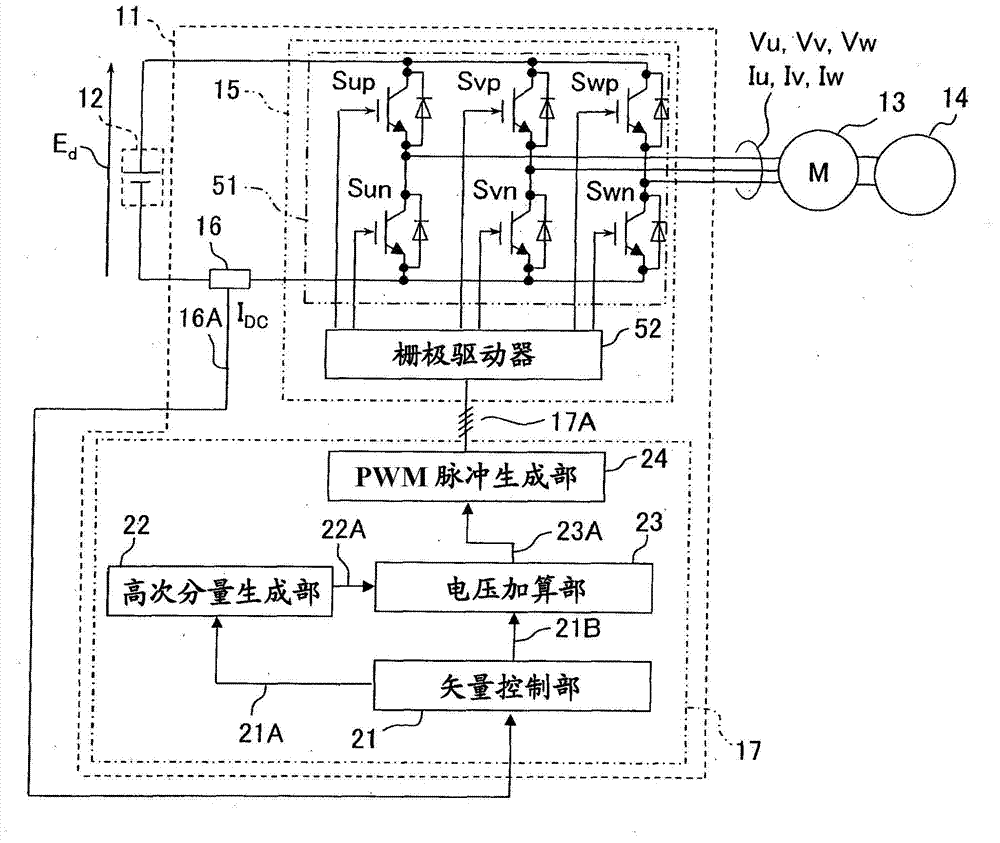
[0049] figure 1 It shows the internal structure of the motor control device 11 according to the first embodiment of the present invention, the motor control device 11, the DC power supply 12, the 3-phase AC synchronous motor (abbreviated as "motor" or "3-phase motor" as appropriate) 13, and the load (Fan) 14 associated diagrams.

[0050] exist figure 1 Among them, the motor control device 11 is configured to include an inverter 15 as a DC-DC power converter and a control device 17 that controls the inverter 15 .

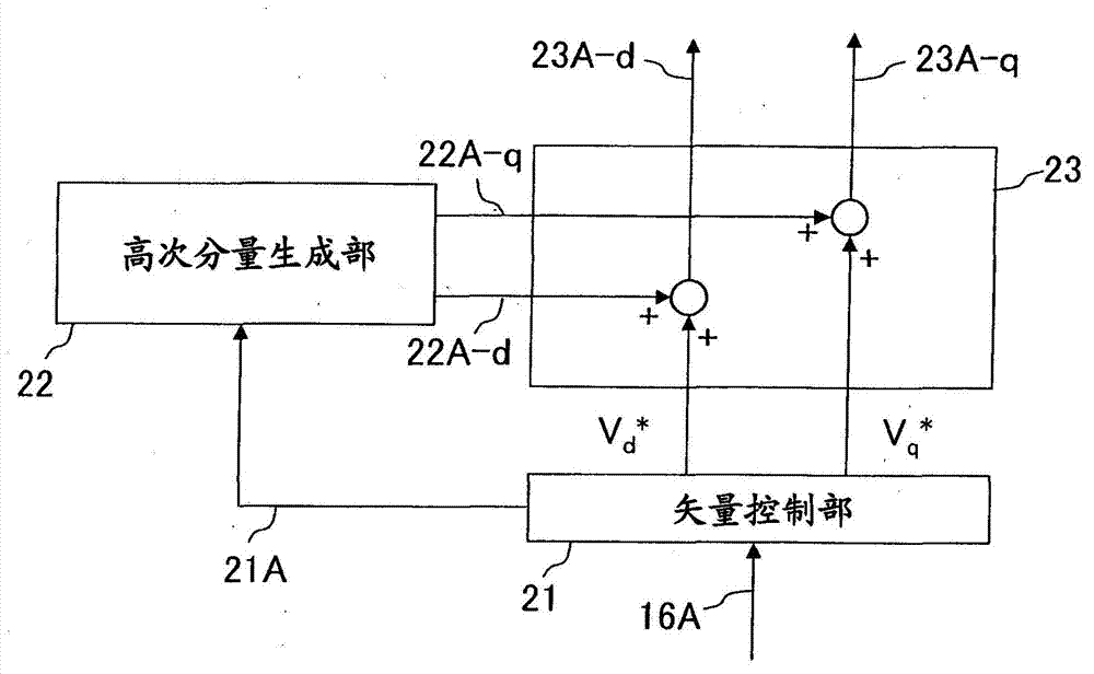
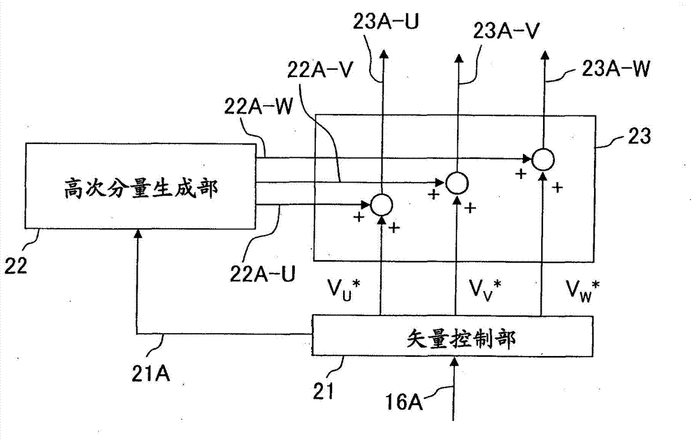
[0051] In addition, the control device 17 is configured to include a PWM (Pulse Width Modulation) pulse generation unit 24 , a vector control unit 21 , a higher-order component generation unit 22 , and a voltage addition unit 23 .

[0052] The motor control device 11 of the ...

no. 2 Embodiment approach )

[0202] refer to Figure 19~Figure 23 , Figure 11 A motor control device according to a second embodiment of the present invention will be described.

[0203] In the second embodiment, the reduction of the generated ninth-order component in the case of adopting the fixed phase 60-degree switching method or the fixed phase 120-degree switching method described later as the modulation method of the PWM control of the three-phase AC motor will be described. , and then reduce the (6m+3) component (m is a positive integer) fan and motor resonance noise method.

[0204] In addition, including the stationary phase 60-degree switching method and the stationary phase 120-degree switching method described later, a method in which one phase potential is fixed at a predetermined electrical angle and the other two phases are modulated is called fixed two-phase modulation.

[0205] First, the stationary phase 60-degree switching method and the stationary phase 120-degree switching method ...

no. 3 Embodiment approach )

[0271] Below, refer to Figure 24 A motor control device according to a third embodiment of the present invention will be described.

[0272] The third embodiment includes the high-order component generation unit 22 and the voltage addition unit 23 of the first embodiment, and the modulation method selection unit 25 of the second embodiment.

[0273]

[0274] Figure 24 It is a figure which shows the internal structure of the motor control device 11 which concerns on 3rd Embodiment of this invention, and the relationship between this motor control device 11, the DC power supply 12, the 3-phase motor 13, and the fan 14.

[0275] exist Figure 24 Among them, the characteristics of the third embodiment exist in the configuration of the control device 20 of the motor control device 11 .

[0276] Moreover, for the DC power supply 12, the motor 13, the fan 14, the inverter 15, and the DC bus current detection circuit 16, because and figure 1 The first embodiment is the same as...


PUM


Abstract

The invention provides a high efficiency motor control device which can reduce noise caused by resonance of a fan and a rotor even though the motor and the fan are not provided with rubber vibration insulators. The motor control device comprises an inverter, a vector control portion, a high-order component generating unit, a voltage adding-up portion, and a PWM pulse generating portion. The inverter is connected with a DC power supply, and the inverter converts DC electricity of the DC power supply to variable-voltage variable frequency AC electricity to drive and control a three-phase motor. The vector control portion calculates voltage applied on the three-phase motor. The high-order component generating unit calculates high-order components of a fundamental wave of the vector control portion applied voltage. The voltage adding-up portion adds the high-order components calculated by the high-order component generating unit to the applied voltage calculated by the vector control portion. Pulse width controls the inverter. The high-order component generating unit generates both of (6m-1) order and (6m+1) order of the fundamental wave component of the three-phase applied voltage, or a high-order component of one of the (6m-1) order and (6m+1) order of the fundamental wave component to apply on the voltage adding-up portion, reducing resonant noise of the three-phase motor at 6m (m is a positive integer) times of rotation frequency.

Description

technical field [0001] The present invention relates to a motor control device and an air conditioner using the motor control device. In particular it relates to the reduction of sound caused by motors for fans. Background technique [0002] Conventionally, in small fan motors used in air conditioners, noise generated at a specific rotational speed due to resonance between the rotor and the fan has been a problem. In order to solve the problem of noise caused by this resonance, anti-vibration rubber is provided on the rotor part, or anti-vibration rubber is provided on the bearing part of the fan to reduce the sound. [0003] One of the reasons for this is the distortion of the current waveform caused by the difference between the distortion of the induced voltage of the motor and the applied voltage, and various methods for removing the distortion of the current waveform have been proposed. [0004] For example, Patent Document 1 discloses a technique in which a voltage f...

Claims


Application Information

Patent Timeline
Patent Type & Authority Applications(China)
IPC IPC(8): H02P21/05H02P27/06H02P6/08H02P6/06H02P6/18H02P6/182H02P6/28H02P21/00H02P21/22H02P23/04H02P27/04H02P27/08
CPCF24F13/24F25B49/025H02P21/05H02P27/08
Inventor 奥山敦初濑渉右子知恵竹田幸二斯瓦潘·比斯沃斯
Owner HITACHI JOHNSON CONTROLS AIR CONDITIONING INC
Why Eureka
Try Eureka