Method for adjusting position of stator

An adjustment method and stator technology, applied in the manufacture of stator/rotor bodies, electromechanical devices, centering/balancing rotors, etc.

Active Publication Date: 2009-12-16
AISIN AW CO LTD +1
View PDF1 Cites 9 Cited by
  • Summary
  • Abstract
  • Description
  • Claims
  • Application Information

AI Technical Summary

Problems solved by technology

[0014] However, it is known that sometimes the stator resonates for som...

Method used


Image

  • Method for adjusting position of stator
  • Method for adjusting position of stator
  • Method for adjusting position of stator

Examples


Embodiment Construction

[0104] In the following description, the structure of the motor drive device M which is the object of the present application, the structure of the stator position adjustment system 100 of the present application for properly assembling the motor drive device M, and the stator S using the stator position adjustment system 100 are discussed. The position adjustment / fixing work of , and the assembly of the motor drive unit M will be described in order.

[0105] 1. Motor drive unit M

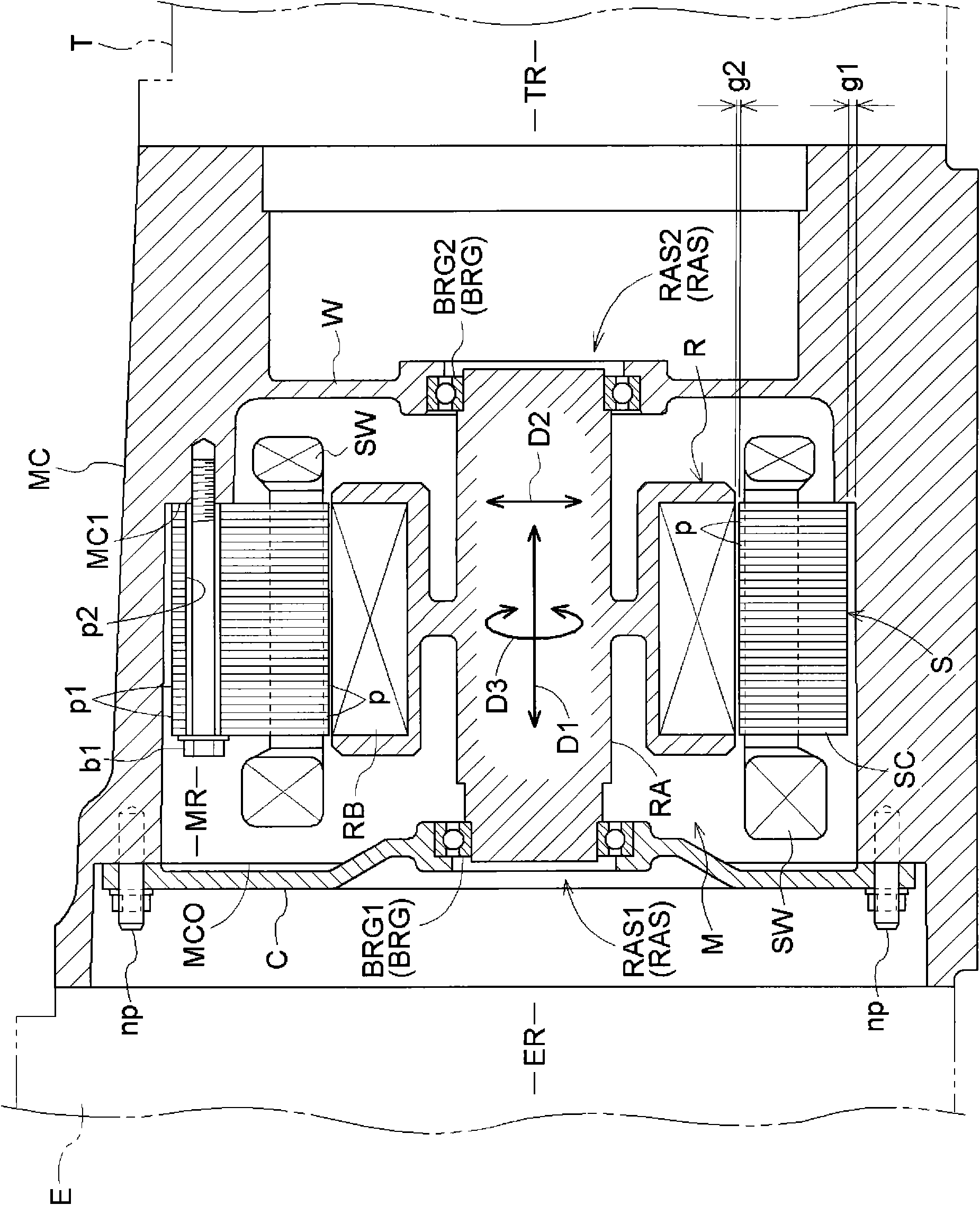
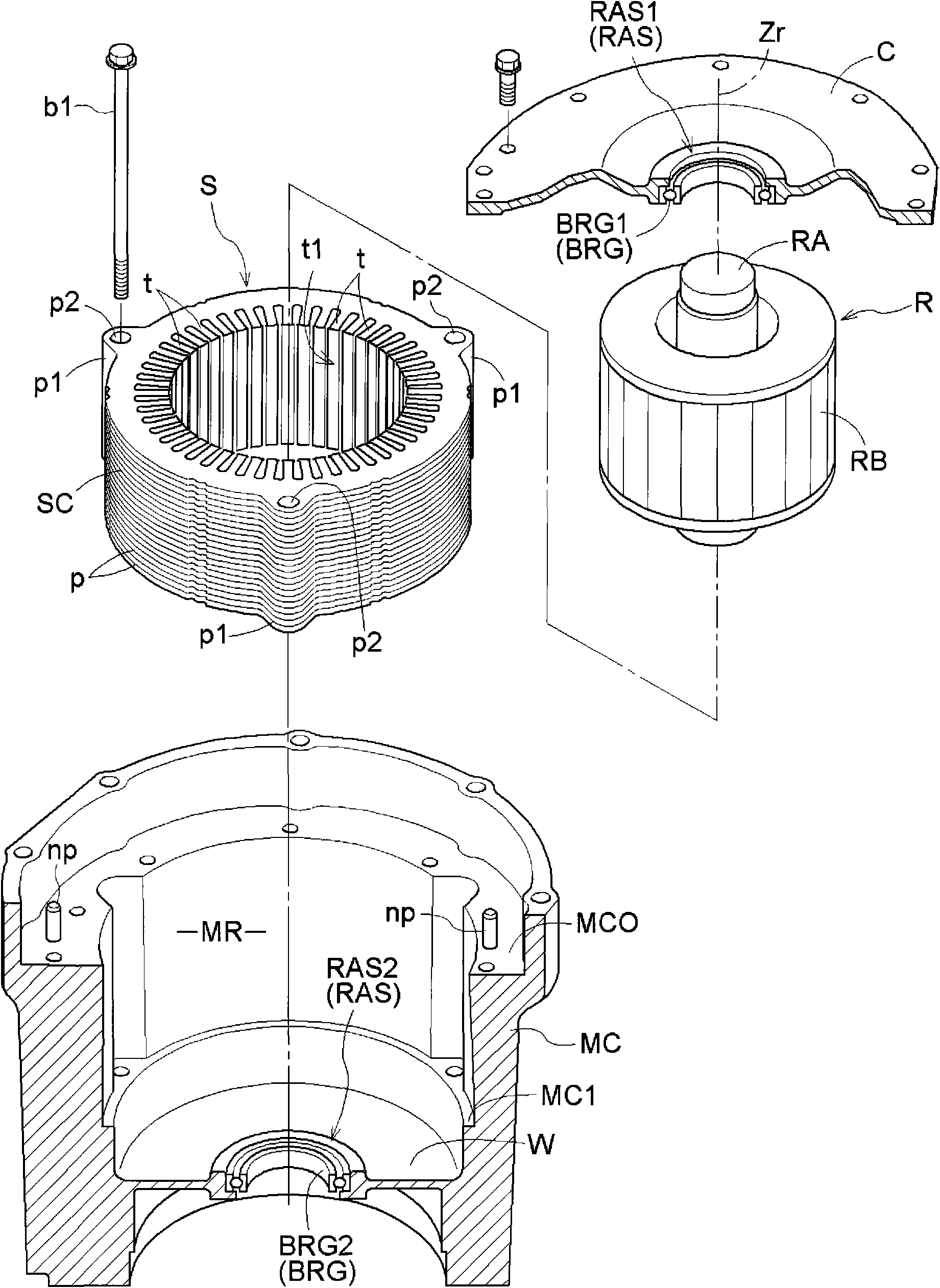
[0106] figure 1 It is a diagram showing a cross-sectional structure of a motor drive device M housed in a gearbox case MC (an example of a motor case) and in an assembled state, figure 2 It is an exploded view showing the motor drive device M in order to clarify the supporting structure of the stator S and the rotor R constituting the motor drive device M.

[0107] exist figure 1 Among them, the left side is a part on the engine room ER side where the engine E is arranged, and the right side is...


PUM


Abstract

With respect to a first allowable range (Tr1) as the maximum allowable range of a stator axis (Zs) in which a first gap (g1) between the outer peripheral surface of a stator and the inner peripheral surface of a motor case is formed and a second allowable range (Tr2) as the maximum allowable range of the stator axis (Zs) in which a second gap (g2) between the inner peripheral surface of the stator and the outer peripheral surface of a rotor is formed, thee first allowable range (Tr1) is set to be same as or smaller than the second allowable range (Tr2). The position of the stator axis (Zs) is measured and is so adjusted that the position of the stator axis (Zs) obtained is kept within the first allowable range (Tr1).

Description

technical field [0001] The present invention relates to a motor housing, a rotor that is pivotally supported by the motor housing and rotates inside, and a stator arranged concentrically with the rotor on the outer periphery of the rotor, and the stator is tightened along the axis of the rotor by means of a A motor drive device fastened and fixed to a motor housing by fastening a unit, relates to a method for adjusting the position of a stator in such a motor drive device, and relates to a stator position adjustment system using the adjustment method. Background technique [0002] Recently, a so-called hybrid vehicle having an engine and a motor drive device as a driving source of an automobile has attracted attention from the viewpoints of fuel consumption and environmental protection. For this kind of hybrid vehicle, the motor drive device not only works as a motor that obtains power from the battery to generate driving force, and transmits its driving force to the side of...

Claims


Application Information

Patent Timeline
IPC IPC(8): H02K15/02H02K15/16
CPCH02K5/15H02K15/16Y10T29/49009Y10T29/49718
Inventor 小栗康德村上智堂广田慈宏矶谷明神野岳人高崎哲水谷龙彦服部宏之
Owner AISIN AW CO LTD
Why Eureka
Try Eureka