Rotary fluid machine

A fluid mechanical and rotary technology, applied in the direction of rotary piston machines, rotary piston pumps, mechanical equipment, etc., can solve problems such as poor efficiency, refrigerant leakage, and failure to consider the gap between the cylinder wall and the piston wall, etc., to achieve Efficiency, leakage suppression effect

Inactive Publication Date: 2007-06-13
DAIKIN IND LTD
View PDF1 Cites 9 Cited by
  • Summary
  • Abstract
  • Description
  • Claims
  • Application Information

AI Technical Summary

Problems solved by technology

[0005] However, conventional fluid machines did not consider the gap between the cylinder wall and the piston wall at all.
As a result, refrigerant leaks from the high-pressure chamber to the low-pressure chamber, resulting in poor efficiency.
[0006] In particular, in the above-mentioned fluid machine, since the outer compression chamber and the inner compression chamber are formed, the load (gas load) due to the pressure of the refrigerant in the outer compression chamber and the inner compression chamber is not considered. act in different directions, resulting in a gap between the cylinder wall and the piston wall

Method used


Image

  • Rotary fluid machine
  • Rotary fluid machine
  • Rotary fluid machine

Examples


Embodiment 1

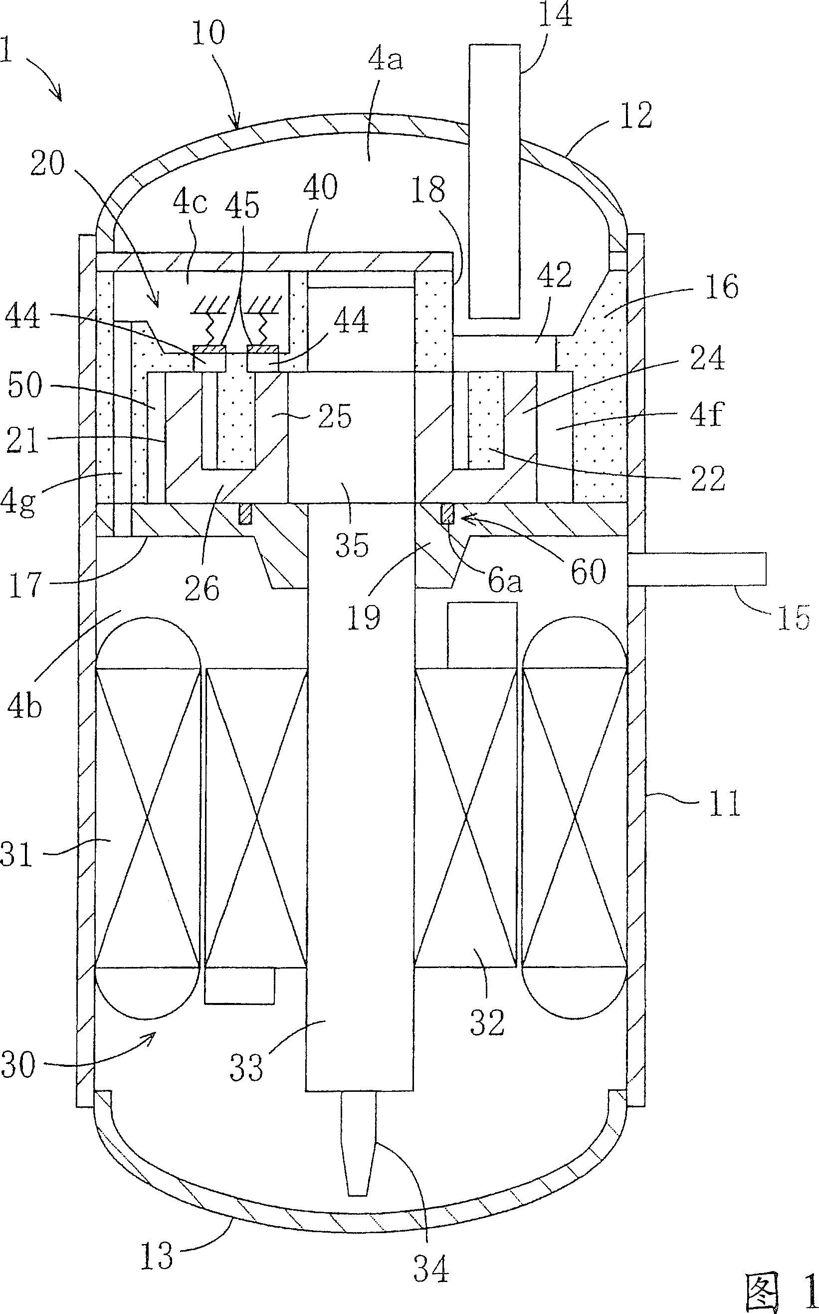
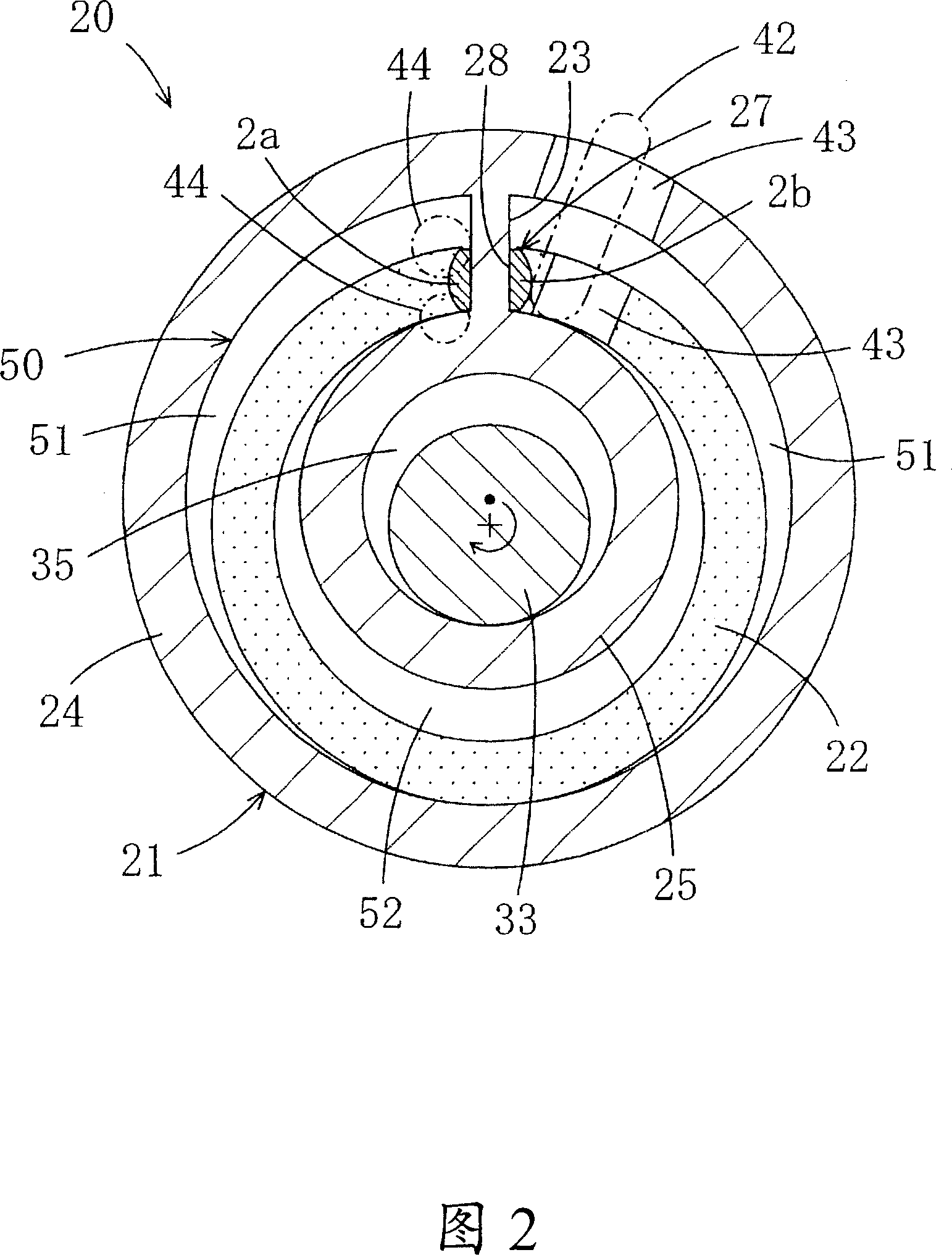
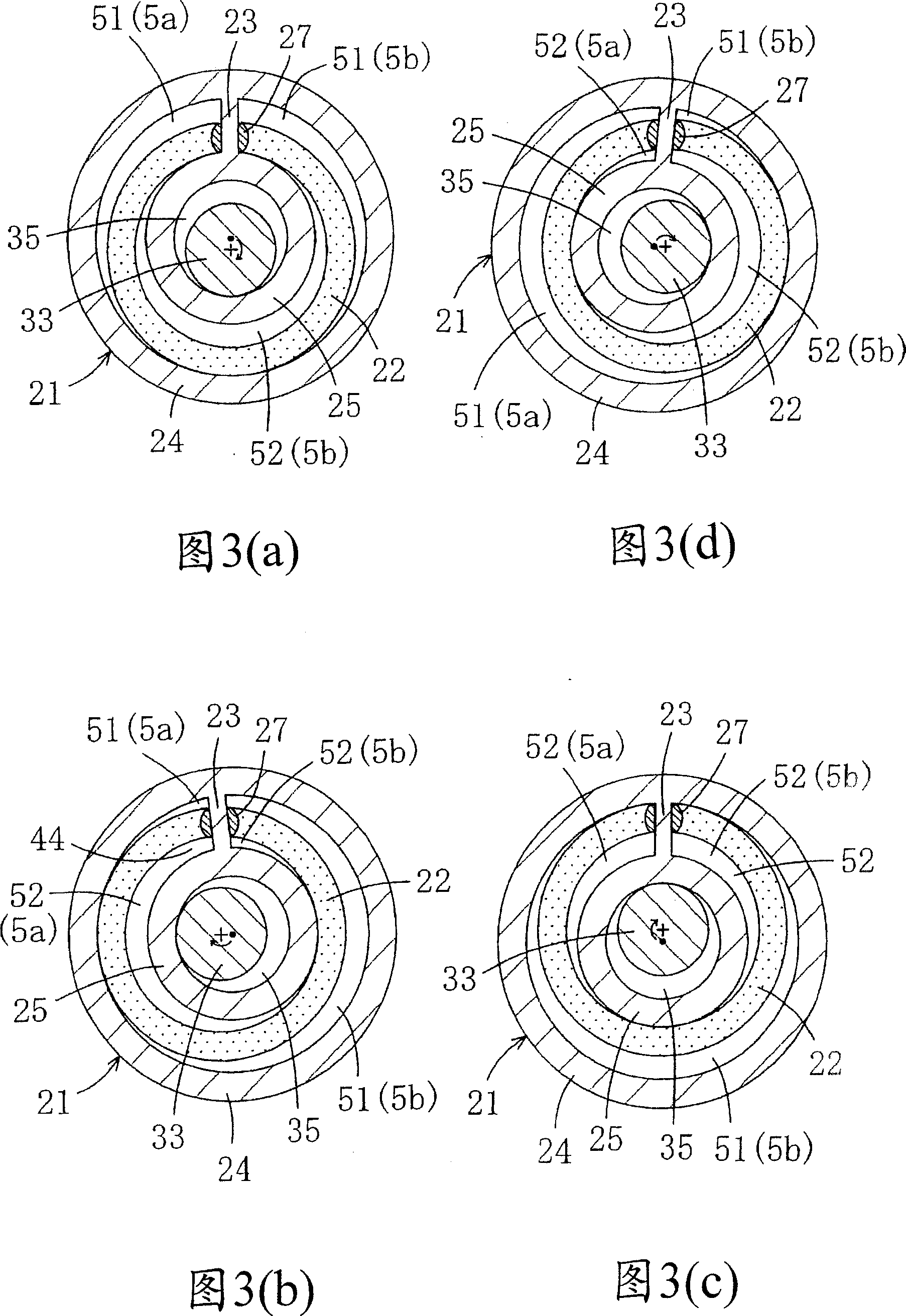
[0063] As shown in FIGS. 1 to 3 , this embodiment stipulates that the present invention is applied to a compressor 1 . The compressor 1 described above is provided in, for example, a refrigerant circuit.

[0064] The refrigerant circuit is configured to perform, for example, at least one of cooling and heating operations. That is, the refrigerant circuit is formed by connecting, for example, an outdoor heat exchanger on the heat source side of the compressor 1, an expansion valve that is an expansion mechanism, and an indoor heat exchanger that is a heat exchanger on the utilization side in the above order. of. And, the refrigerant compressed in the compressor 1 expands in the expansion valve after dissipating heat in the outdoor heat exchanger. The expanded refrigerant absorbs heat in the indoor heat exchanger and returns to the compressor 1 . This cycle is repeated, and the indoor air is cooled by the indoor heat exchanger.

[0065] The above-mentioned compressor 1 is a ...

Embodiment 2

[0121] Next, Embodiment 2 of the present invention will be described in detail with reference to the accompanying drawings.

[0122] In the first embodiment above, the width T1 of the cylinder chamber and the width T2 of the piston are changed in two areas, instead, this embodiment is made to change in four areas, as shown in FIGS. 7 to 9 .

[0123] Specifically, the cylinder chamber 50 is divided into four regions on the circumference, and the wide regions Z1 and Z3 with wide widths and the narrow regions Z2 and Z4 with narrow widths are alternately connected to each other. On the other hand, the piston 22 is divided into four regions on the circumference, and the narrow narrow regions W1, W3 and the wide wide regions W2, W4 are alternately connected to each other.

[0124] That is, in the cylinder chamber 50 , as shown in FIG. 7 , a first region Z1 is formed as a wide region Z1 in a range of 90 degrees across the vane 23 . Starting from the above-mentioned first zone portio...


PUM


Abstract

A rotary fluid machine, comprising a cylinder (21) having an annular cylinder chamber (50), an annular piston (22) stored in the cylinder chamber (50) eccentrically to the cylinder (21) and partitioning the cylinder chamber (50) into an outer compression chamber (51) and an inner compression chamber (52), and a blade (23) disposed in the cylinder chamber (50) and partitioning the compression chambers (51) and (52) into a high-pressure side and a low-pressure side. The rotary fluid machine also comprises a rotating mechanism (20) for rotating the cylinder (21) and the piston (22) relative to each other. The cylinder chamber (50) is so formed that the width (T1) of the cylinder chamber (50) is varied in one rotation of the cylinder chamber (50) so that a clearance between the wall surface of the cylinder (21) and the wall surface of the piston (22) in rotation becomes a specified value. Also, the piston (22) is so formed that the width (T2) of the piston (22) is varied in one rotation of the piston (22) so that the clearance between the wall surface of the cylinder (21) and the wall surface of the piston (22) in rotation becomes the specified value.

Description

technical field [0001] The invention relates to a rotary fluid machine, in particular to a rotary fluid machine which solves the problem of the gap between the cylinder and the piston. Background technique [0002] Conventionally, as disclosed in Patent Document 1, a fluid machine has a compressor including an eccentrically rotating piston mechanism including a cylinder having an annular cylinder chamber and an eccentrically arranged cylinder housed in the cylinder chamber. Rotary ring piston. In addition, the above-mentioned fluid machine compresses the refrigerant by changing the volume of the cylinder chamber accompanying the eccentric rotational movement of the piston. [0003] [Patent Document 1] Patent Publication No. Hei 6-288358 (Hei 6 = Heisei 6 / 1994) [0004] (The problem to be solved by the invention) [0005] However, in conventional fluid machines, no consideration was given to the gap created between the cylinder wall surface and the piston wall surface. As...

Claims


Application Information

Patent Timeline
Patent Type & Authority Applications(China)
IPC IPC(8): F04C18/32F04C29/00F01C21/08F04C23/00
CPCF04C23/001F01C21/08F04C23/008F04C2240/20F04C2230/602F04C18/045F04C18/02F04C18/32
Inventor 增田正典
Owner DAIKIN IND LTD
Why Eureka
Try Eureka