Actuating mechanism and brake assembly

A technology of actuating mechanism and components, applied in the direction of brake actuator, gear shifting mechanism, mechanical equipment, etc., can solve the problems of insufficient lubrication of gear mechanism, affecting the performance of rotor and stator, etc.

Inactive Publication Date: 2007-06-13
PBR AUSTRALIA PTY LTD
View PDF2 Cites 7 Cited by
  • Summary
  • Abstract
  • Description
  • Claims
  • Application Information

AI Technical Summary

Problems solved by technology

This affects the performance of both the rotor and the st...

Method used


Image

  • Actuating mechanism and brake assembly
  • Actuating mechanism and brake assembly
  • Actuating mechanism and brake assembly

Examples


Embodiment Construction

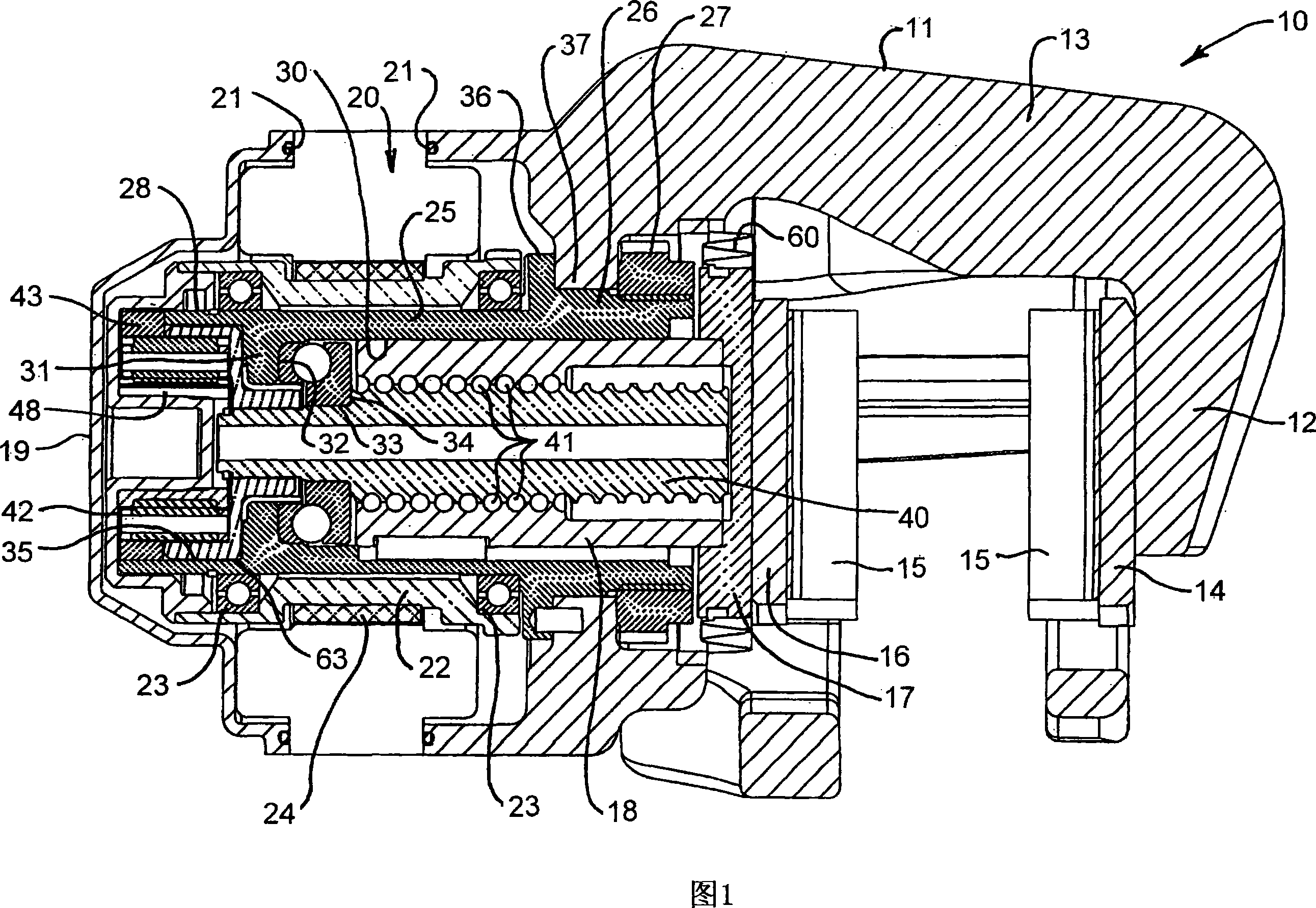
[0032] FIG. 1 shows a disc brake caliper 10 comprising a housing 11 with fingers 12 arranged substantially perpendicularly to a bridge 13 of the housing 11 . The finger 12 supports a first brake pad 14 with a friction lining 15 . A further brake shoe 16 having a similar or identical friction lining 15 is in abutting engagement with a head 17 fixed to one end of a nut 18 . As will be apparent later in the discussion, the nut 18 is operable to move axially to displace the head 17 and the brake pad 16 so that the friction lining 15 of the brake pad 16 is in contact with the friction lining 15 disposed between the block 14 and the block 16. The rotor (not shown) between them is engaged, after which the caliper is arranged such that the other friction lining 15 engages the opposite rotor side.

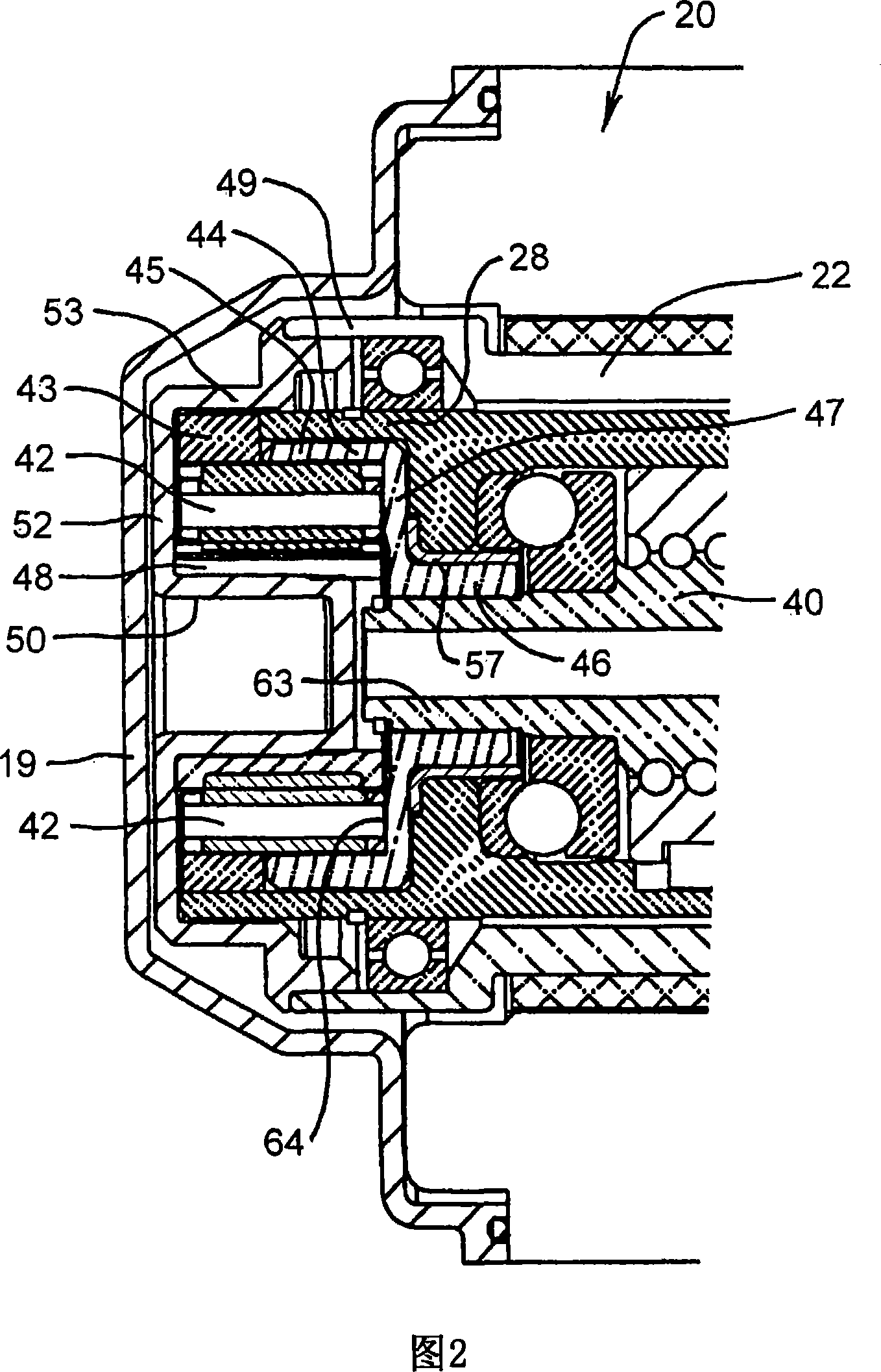
[0033] The housing 11 houses a stator 20 fixed within the housing 11 and sealed therein by an O-ring seal 21 . The housing 11 comprises a housing cover 19 which is fixed in place in a sui...


PUM


Abstract

An actuating mechanism, particularly for a disc brake caliper, including a screw actuator having a screw (40) and a nut (18) threadably coupled together, an electric drive for driving one of the screw (40) and the nut (18) axially relative to the other and including a stator (20) and a rotor (22), a sleeve assembly including a generally cylindrical sleeve (25) interposed between the rotor (22) and the nut (18) and supporting the rotor (22) for rotation relative to the sleeve (25). The rotor (22) is connected to one of the screw (40) or the nut (18) for rotating the screw (40) or the nut (18). The screw actuator being at least partly mounted within the sleeve (25) and being arranged to bear against a portion of the sleeve assembly to transmit axial thrust to the sleeve assembly, and the sleeve assembly cooperating with an abutment to transmit the axial thrust to the abutment.

Description

technical field [0001] The present invention relates to an actuating mechanism, in particular for a brake assembly, in particular for a disc brake assembly. Therefore, while it is convenient to discuss and describe the invention in relation to a specific application, it should be noted that the invention has broader application in fields other than disc brakes. Background technique [0002] The actuating mechanism of the present invention is electrically operated and has been developed for service brakes and / or parking brakes. However, many of today's developments utilizing electrical actuation have resulted in brake assemblies that are too bulky and / or too long to fit within vehicle spaces that were previously manufactured for non-electric, hydraulically operated brakes. Furthermore, the actuating mechanism must be arranged to be operable under brake loading conditions, in particular during deformation of the caliper housing. The aforementioned deformations can lead to mi...

Claims


Application Information

Patent Timeline
IPC IPC(8): F16D65/14F16D65/18
CPCF16D65/18Y10T74/19702F16D2125/50F16D2125/40Y10T74/18664F16D2121/24
Inventor 汪磊阿纳托利·卡加诺夫西蒙·科德安德斯·克努岑
Owner PBR AUSTRALIA PTY LTD
Why Eureka
Try Eureka