Manufacture method of a latent heat recovery type heat exchanger

A heat recovery type, heat exchanger technology, applied in the direction of heat exchanger fixation, heat exchange equipment, manufacturing tools, etc., can solve problems such as stress corrosion cracks, achieve the effect of reducing the number of parts and reducing manufacturing costs

Inactive Publication Date: 2007-06-20
RINNAI CORP
View PDF1 Cites 22 Cited by
  • Summary
  • Abstract
  • Description
  • Claims
  • Application Information

AI Technical Summary

Problems solved by technology

However, if such a heat-absorbing tube is bent into a meandering shape withou...

Method used


Image

  • Manufacture method of a latent heat recovery type heat exchanger
  • Manufacture method of a latent heat recovery type heat exchanger
  • Manufacture method of a latent heat recovery type heat exchanger

Examples


Embodiment Construction

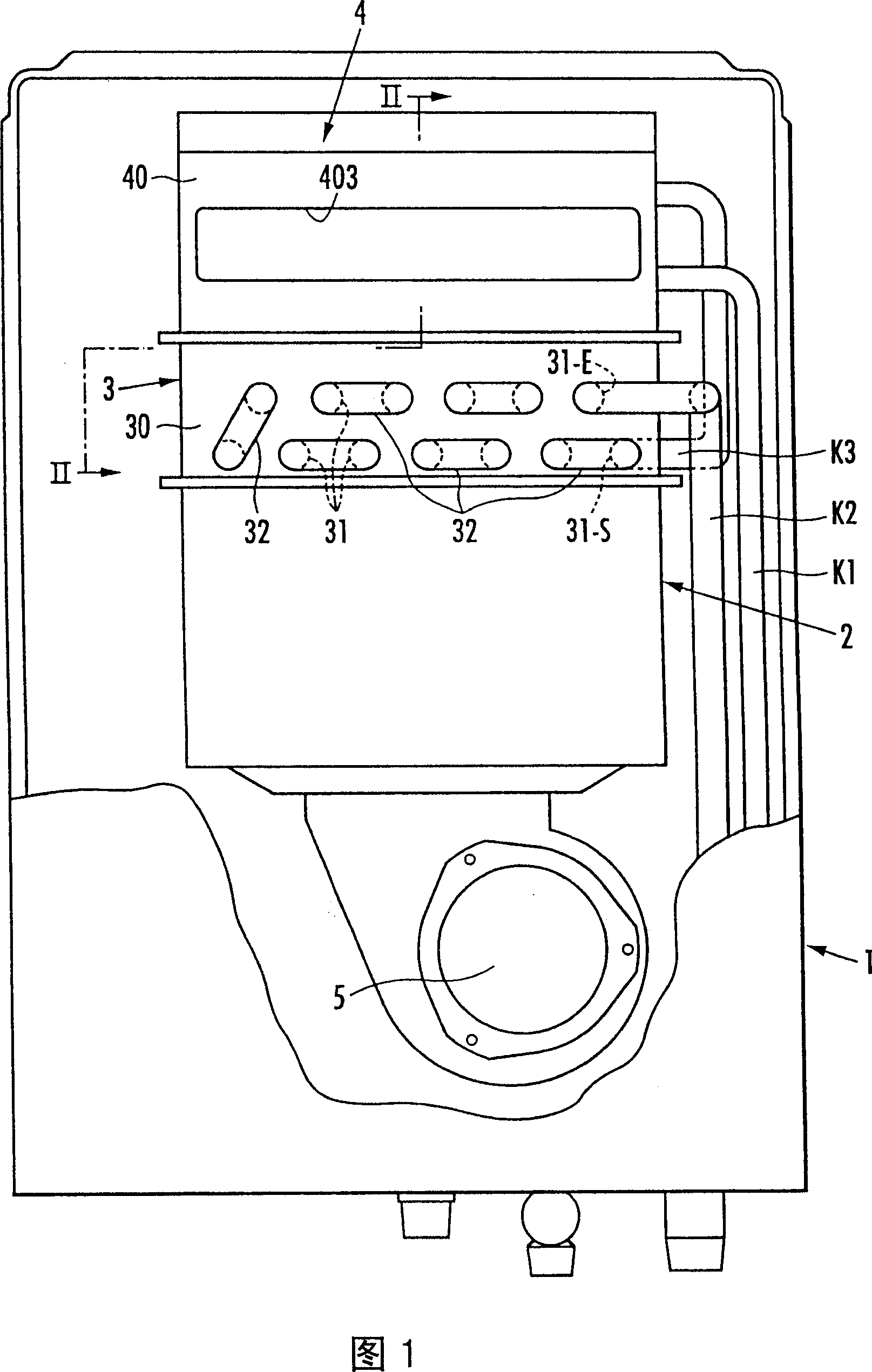
[0018] Referring to Fig. 1, 1 is the outer casing of the water heater, and the outer casing 1 is equipped with: a combustion basket 2 with a built-in burner (not shown), a main heat exchanger 3 above the combustion basket 2, and a main heat exchanger The secondary heat exchanger 4 above the device 3. In addition, a combustion blower 5 for supplying combustion air into the combustion basket 2 is arranged on the lower side of the combustion basket 2 .

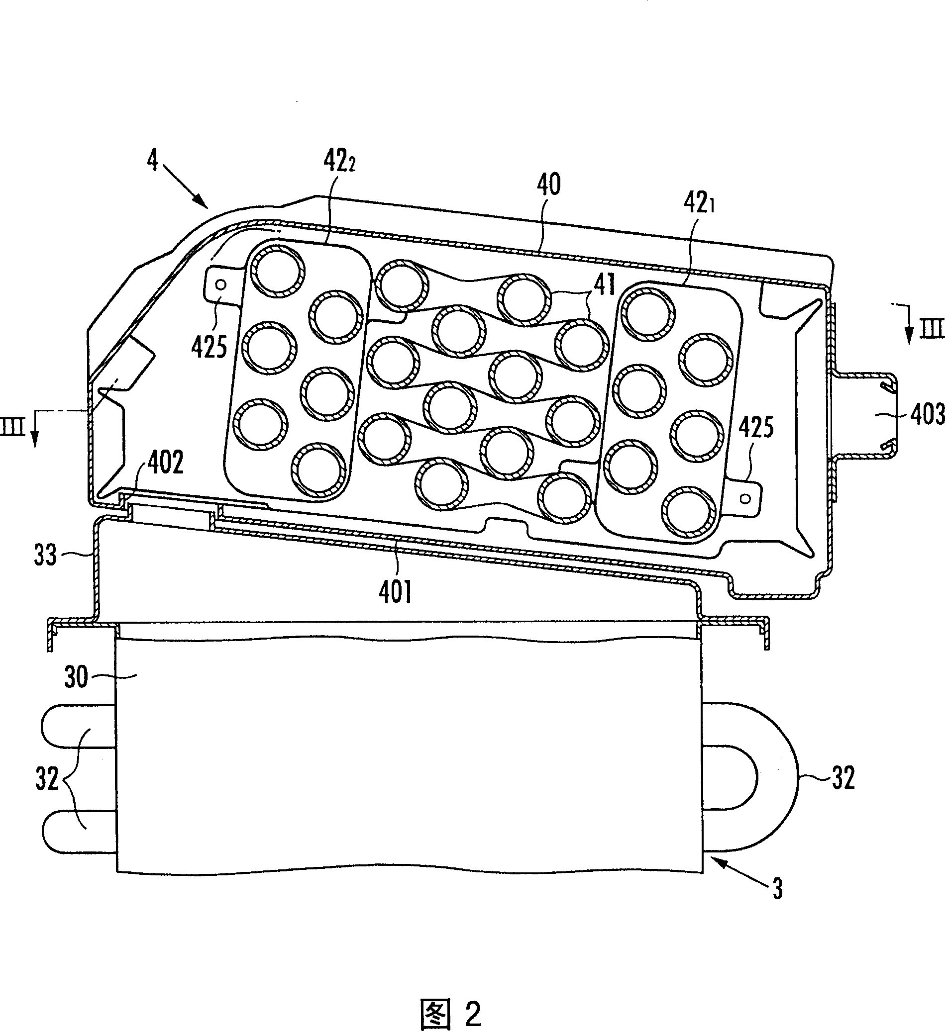
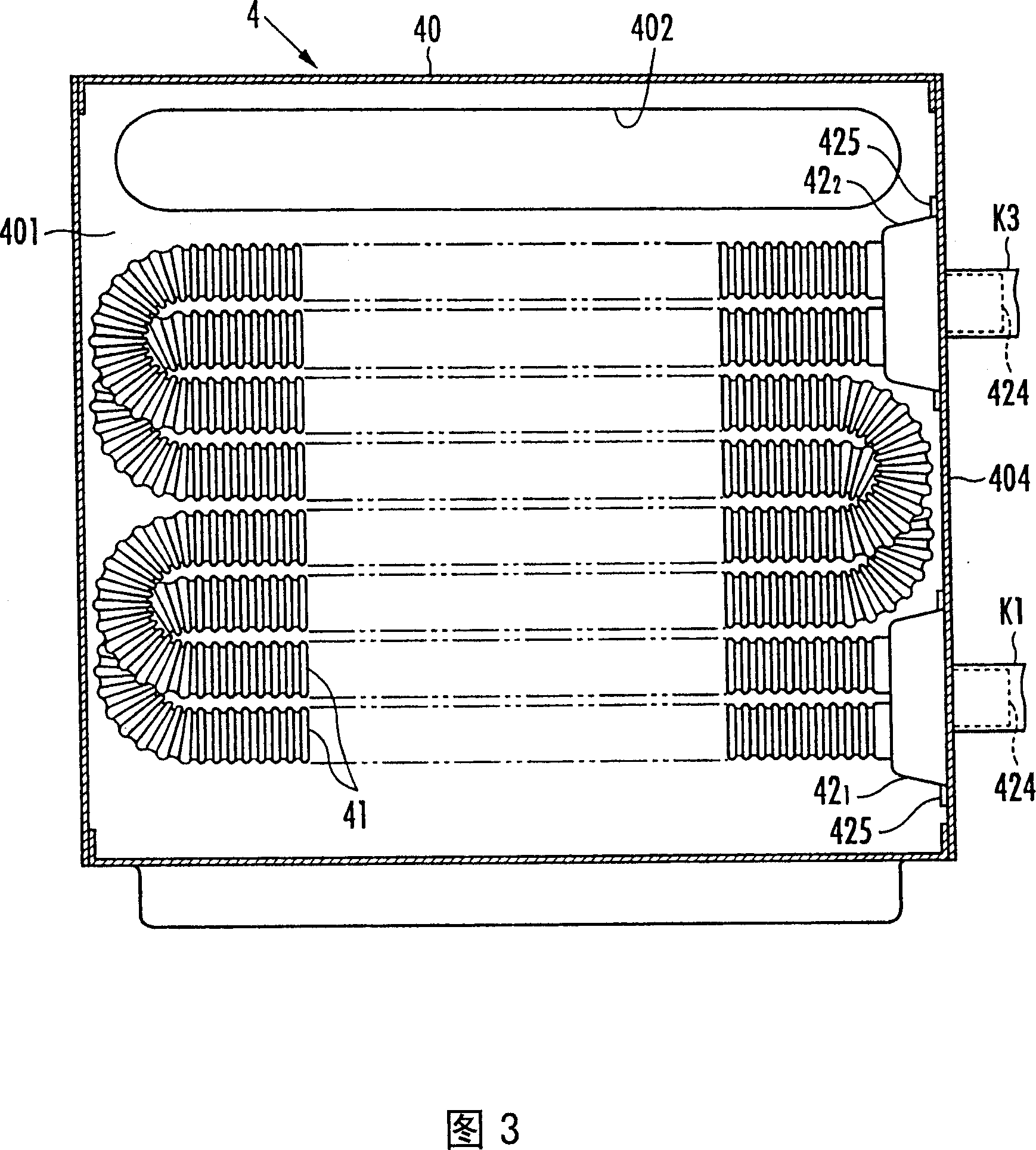
[0019] The main heat exchanger 3 is provided with a plurality of heat-absorbing fins (not shown) stacked so that there are gaps in the front-rear direction (vertical direction to the paper surface of FIG. ), a plurality of heat-absorbing pipes 31 that pass through these heat-absorbing sheets and are arranged in the longitudinal direction with the front-rear direction as its longer direction. And, on the outside of the front and rear plates of the trunk portion 30, as shown in Figure 1 and Figure 2, the heat absorption pipe 31 of...


PUM


Abstract

A manufacture method of a latent heat recovery type heat exchanger. A plurality of heat absorbing snake pipes is provied in a body for flowing combustion discharging air. One end of the heat absorbing pipes is connected to an inflow assemble and the other end is connected to an outflow assemble so that the fluid to be heated can flow to the outflow assemble from the inflow assemble via the heat absorbing pipes. Thus, it is possible to manufacture a latent heat recovery type heat exchanger for recovering a latent heat in a cost as low as possible by coagulating the water vapour of the combustion discharging air outside the absorbing pipes and then recovering the latent heat. One and the other end of the plurality of the heat absorbing snake pipes are inserted into the inflow assemble (421), the outflow assemble (422), respectively, after assembled, an auxiliary assembling device is then thrown into a furnace to perform soldering in a furnace for soldering each end of the absorbing pipes (41) on the inflow assemble (421, 422). In addition, heat treatment is implemented in the furnace braze soldering process to remove the residual stress from the absorbing pipes (41).

Description

technical field [0001] The present invention relates to a method of manufacturing a latent heat recovery type heat exchanger for condensing water vapor in combustion exhaust gas to recover latent heat. Background technique [0002] Conventionally, as this type of latent heat recovery type heat exchanger, a plurality of serpentine heat absorbing pipes are arranged in the body where the combustion exhaust gas flows, and one end and the other end of these heat absorbing pipes are respectively connected to the inflow manifold. Parts and outflow collection parts, so that the heated fluid flows from the inflow collection parts to the outflow collection parts through these heat absorption pipes, so that the water vapor in the combustion exhaust gas is condensed outside the heat absorption pipes, and the latent heat is recovered (for example, refer to JP-A-2004 -271109 Bulletin). [0003] In this device, each assembly is a cast product, and a cylindrical insertion port for a heat a...

Claims


Application Information

Patent Timeline
IPC IPC(8): B23P15/26B23K1/008C21D9/50C21D1/30F28F9/26F28D1/047
CPCB21D53/02F28D7/082F28F2275/04
Inventor 后藤真一成濑英克
Owner RINNAI CORP
Why Eureka
Try Eureka