

Intermediate cooler setting structure with supercharge equipment engine
A cooler and engine technology, which is applied in the direction of engine cooling, machine/engine, power plant cooling combination layout, etc., which can solve the problems such as the wind is not easy to leak, the cooling efficiency of the intercooler is reduced, etc.
- Summary
- Abstract
- Description
- Claims
- Application Information
AI Technical Summary
Problems solved by technology
Method used
Image

Examples
Embodiment Construction
[0072] The embodiments will be described in detail below in conjunction with the accompanying drawings.
[0073] 1 to 15 show embodiments of the present invention.
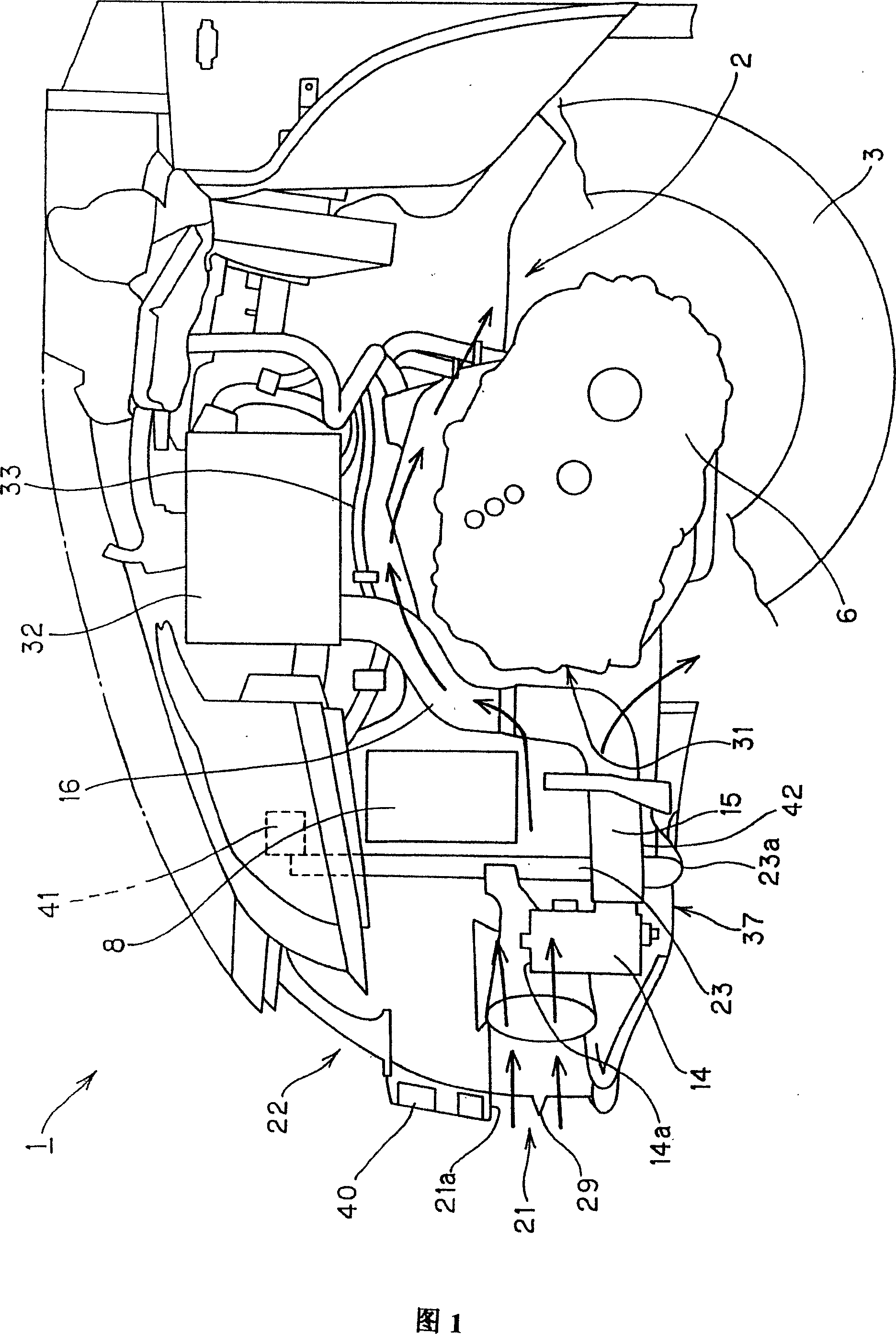
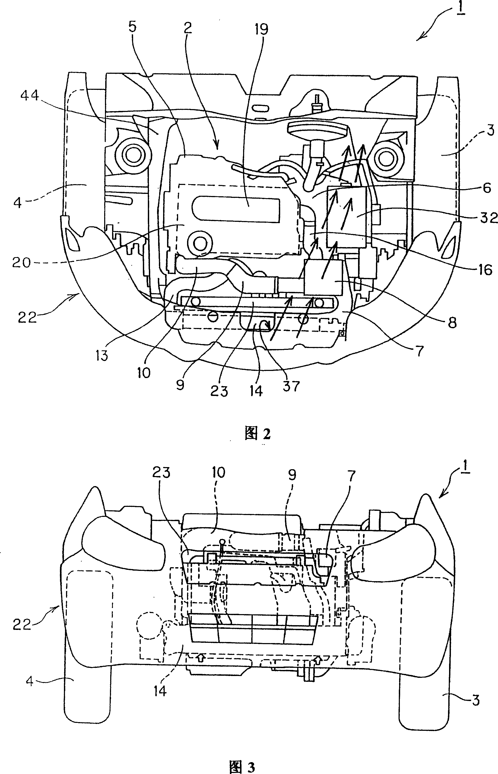
[0074] 1 to 3 , 1 is a vehicle, 2 is an engine compartment formed on the front side of the vehicle 1 , 3 is a left front wheel of the vehicle 1 , and 4 is a right front wheel of the vehicle 1 .
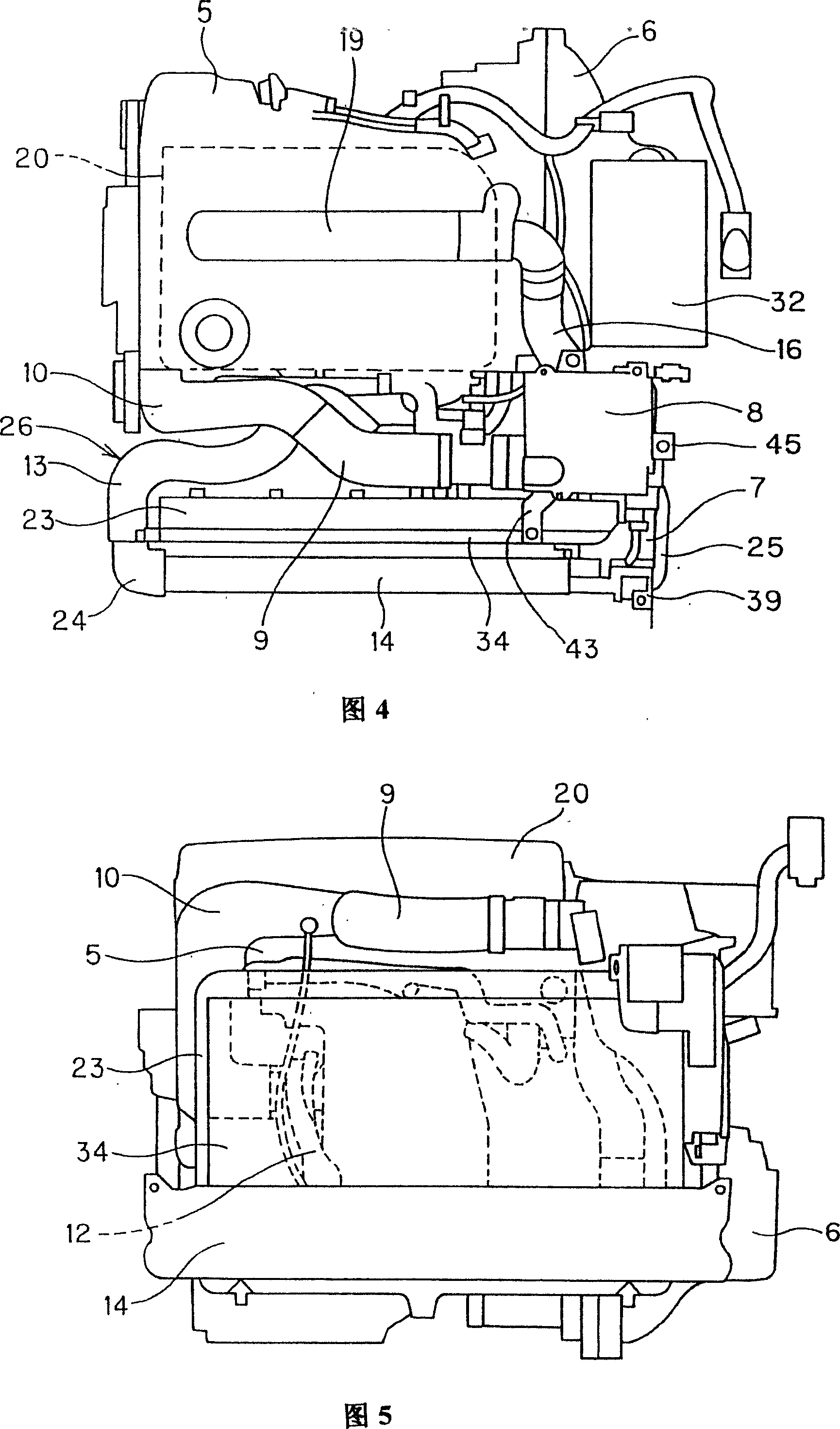
[0075] Furthermore, in the engine room 2 of the vehicle 1, the supercharged engine 5 and the transmission 6 are arranged side by side in the vehicle lateral direction.
[0076] That is, as shown in FIG. 2 , a supercharged engine 5 is mounted in a horizontal state in an engine room 2 of the vehicle 1 , and a transmission 6 is provided on a side of the supercharged engine 5 . At this time, the height of the transmission 6 is lower than that of the engine 5 with a supercharger, and since there are many gaps above the transmission 6 , a large amount of traveling air flows from the engine 5 with a supercharger to the transmis...
PUM
 Abstract
Description
Claims
Application Information