rotating electrical machine

A technology for rotating electrical machines and rotors, applied in the field of rotating electrical machines, can solve the problems of insufficient cooling of permanent magnets, complex shapes of casings, and complex shapes of rotor shafts.

Active Publication Date: 2019-08-30
HONDA MOTOR CO LTD
View PDF5 Cites 0 Cited by
  • Summary
  • Abstract
  • Description
  • Claims
  • Application Information

AI Technical Summary

Problems solved by technology

[0010] However, in the structure described in Patent Document 1, since the refrigerant is carried by the gears, a collection tank is required, and the shape of the casing becomes complicated, and the shape of the rotor shaft also becomes complicated.
[0011] In addition, in the structure described in Patent Document 2, the permanent magnets cannot be sufficiently cooled, and the shape of the rotor shaft becomes complicated for oil supply to the shaft center, and a hydraulic pump and a refrigerant ejection device need to be separately installed.

Method used


Image

  • rotating electrical machine
  • rotating electrical machine
  • rotating electrical machine

Examples


Embodiment Construction

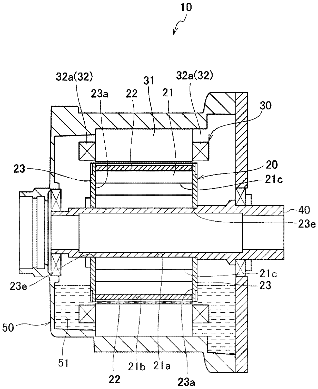
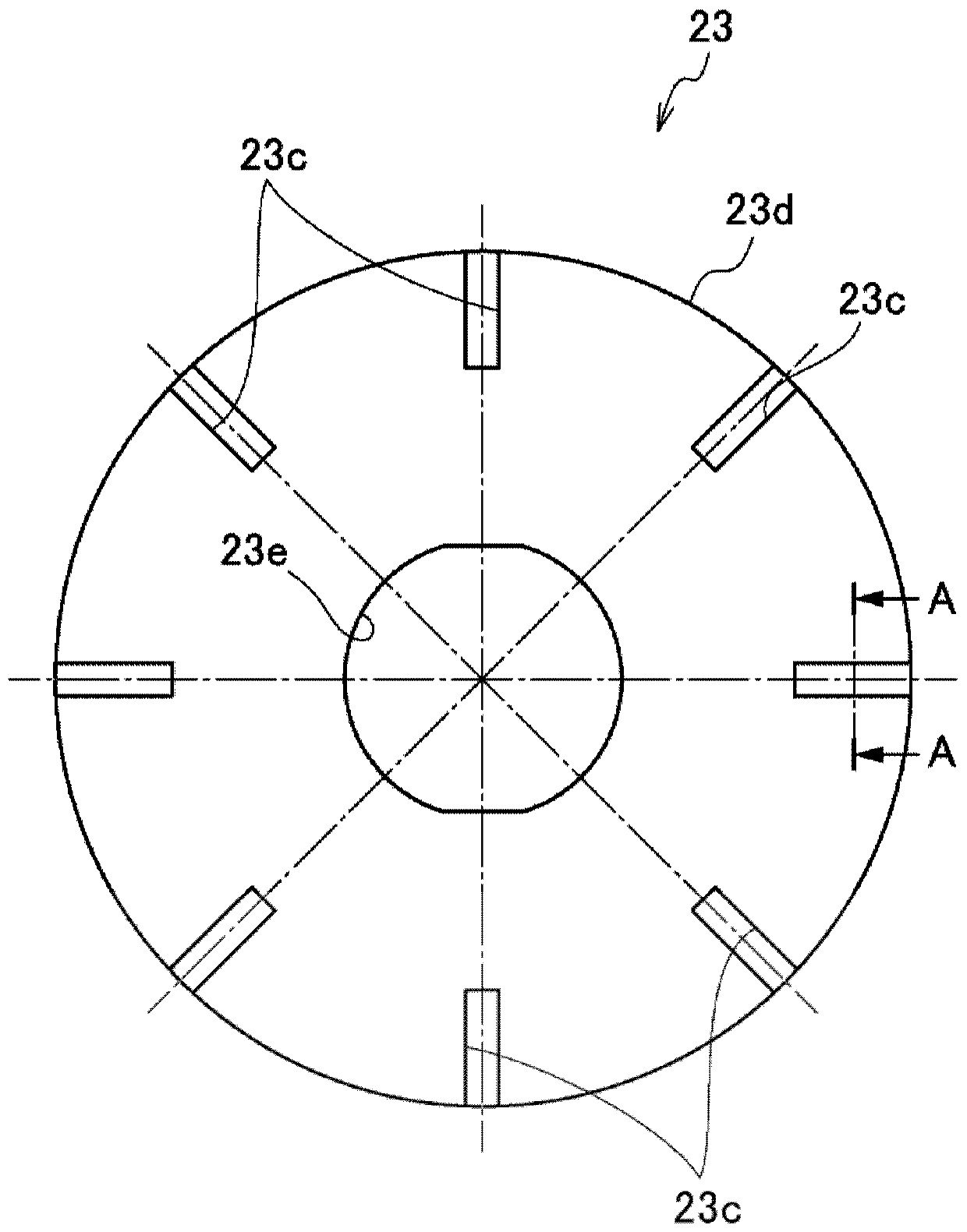
[0074] Below, according to Figures 1 to 5A and Figure 5B , an embodiment of the rotating electrical machine of the present invention will be described. In addition, the drawings are viewed along the direction of the symbols.

[0075] [rotating motor]

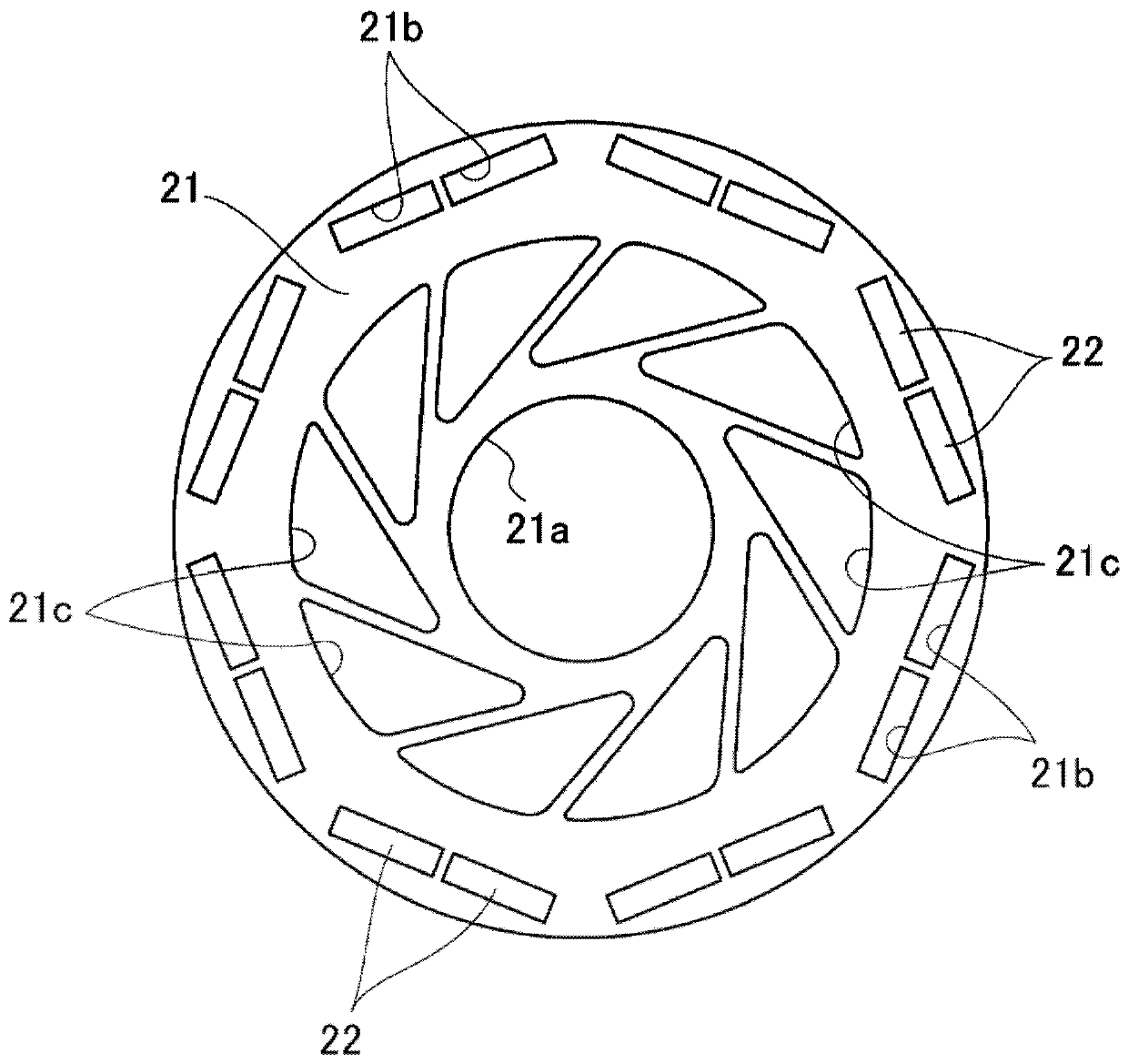
[0076] Such as figure 1 As shown, the rotating electric machine 10 according to the present embodiment is a so-called inner rotor type rotating electric machine, which includes a rotor 20, a stator 30 disposed opposite to the outer peripheral side of the rotor 20 with a slight gap therebetween, and is integrated with the rotor 20. A rotor shaft 40 is rotatably attached to the inner peripheral portion of the rotor 20 , and a housing 50 that accommodates the rotor 20 and the stator 30 and supports the rotor shaft 40 rotatably.

[0077] [case]

[0078] The housing 50 has a substantially cylindrical shape, and the stator 30 is fixed to the inner peripheral portion. The lower part of the housing 50 becomes a storage part 51 w...


PUM


Abstract

The present invention provides a rotating electrical machine capable of efficiently cooling permanent magnets and coils with a simple structure. A rotating electric machine (10) includes a rotor (20) having a rotor core (21), a plurality of permanent magnets (22) arranged on the rotor core (21), and an inner surface (23a) arranged so that the rotor core ( 21) an end plate (23) in contact with the end surface; a stator (30), which has a stator core (31) and a coil (32) configured on the stator core (31), and the stator (30) is placed on the rotor (20 ) is disposed so as to face the rotor (20); and a housing (50) that accommodates the rotor (20) and the stator (30) and has a storage portion (51) that stores liquid inside. The lower part of the rotor (20) is immersed in the storage part (51), and on the end plate (23), a liquid guide groove (23c) or a liquid guide hole (23f) extending radially is provided on the outer surface (23b).

Description

technical field [0001] The present invention relates to a rotating electrical machine that can be mounted on a vehicle or the like. Background technique [0002] In recent years, in a hybrid vehicle or an EV vehicle using a rotating electric machine as a drive source, temperature rises of permanent magnets and coils, which greatly affect the performance of the rotating electric machine, have become a problem, and efficient cooling has become a problem. [0003] In the driving device described in Patent Document 1, it is described that the refrigerant is supplied to the permanent magnet and the coil through the refrigerant passage formed inside the end plate from the collecting tank, wherein the collecting tank receives the refrigerant driven by the gear. The refrigerant. Furthermore, it is described that when supplying the refrigerant to the refrigerant passage formed inside the end plate, a notch is formed in the flange portion supporting the rotor shaft of the end plate, ...

Claims


Application Information

Patent Timeline
Patent Type & Authority Patents(China)
IPC IPC(8): H02K9/19H02K1/32H02K1/27H02K3/24
CPCH02K1/2706H02K1/32H02K3/24H02K9/19H02K1/276H02K1/16H02K1/274H02K3/48H02K5/04
Inventor 西田笃史矢崎学林信章
Owner HONDA MOTOR CO LTD
Why Eureka
Try Eureka