

Magnetic heat dissipation device
A technology of heat dissipation device and magnetic force, applied in electromechanical devices, modification by conduction heat transfer, cooling/ventilation/heating renovation, etc. The effect of efficiency
- Summary
- Abstract
- Description
- Claims
- Application Information
AI Technical Summary
Problems solved by technology
Method used
Image

Examples
Embodiment 1
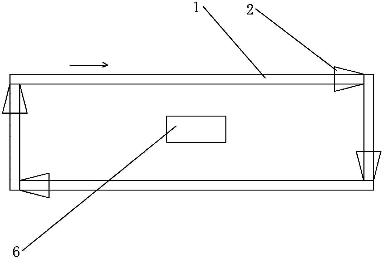
[0021] The cooling device includes an annular sealing pipeline 1, and magnetic liquid is housed in the said annular sealing pipeline 1; said annular sealing pipeline 1 has at least one trumpet-shaped electrified solenoid 2; said annular sealing pipeline Road 1 includes at least one heat absorption section and at least one heat dissipation section. The heat-absorbing section is close to the heat source 6 and absorbs heat; the heat-dissipating section is far away from the heat source 6 and emits heat.
[0022] Direct current is passed into the described energized solenoid 2, and the energized solenoid 2 has a small end and a large end; if there are multiple energized solenoids 2 on the annular sealed pipeline 1, each energized solenoid The small ends of 2 all point to the clockwise or counterclockwise direction of the annular sealed pipeline 1, and the direction of the current flowing into all the energized solenoids 2 is the same. To ensure that all energized solenoids 2 push ...
Embodiment 2
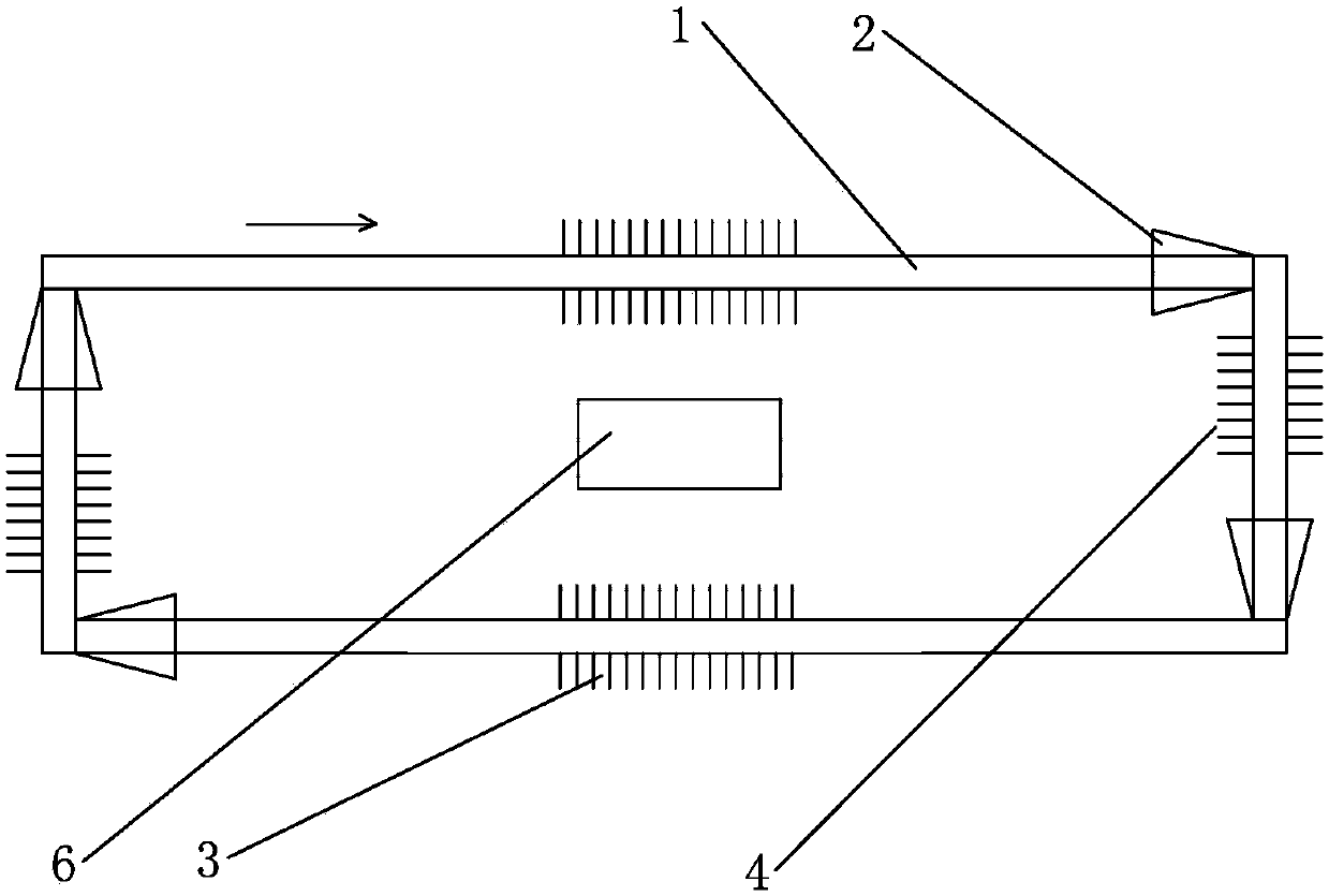
[0026] On the basis of Embodiment 1, the heat dissipation device of this embodiment also includes:
[0027] The heat absorbing section includes heat absorbing fins 3 .
[0028] The heat dissipation section includes heat dissipation fins 4 .
[0029] The heat-absorbing fins 3 and heat-dissipating fins 4 are made of non-magnetic materials.
Embodiment 3
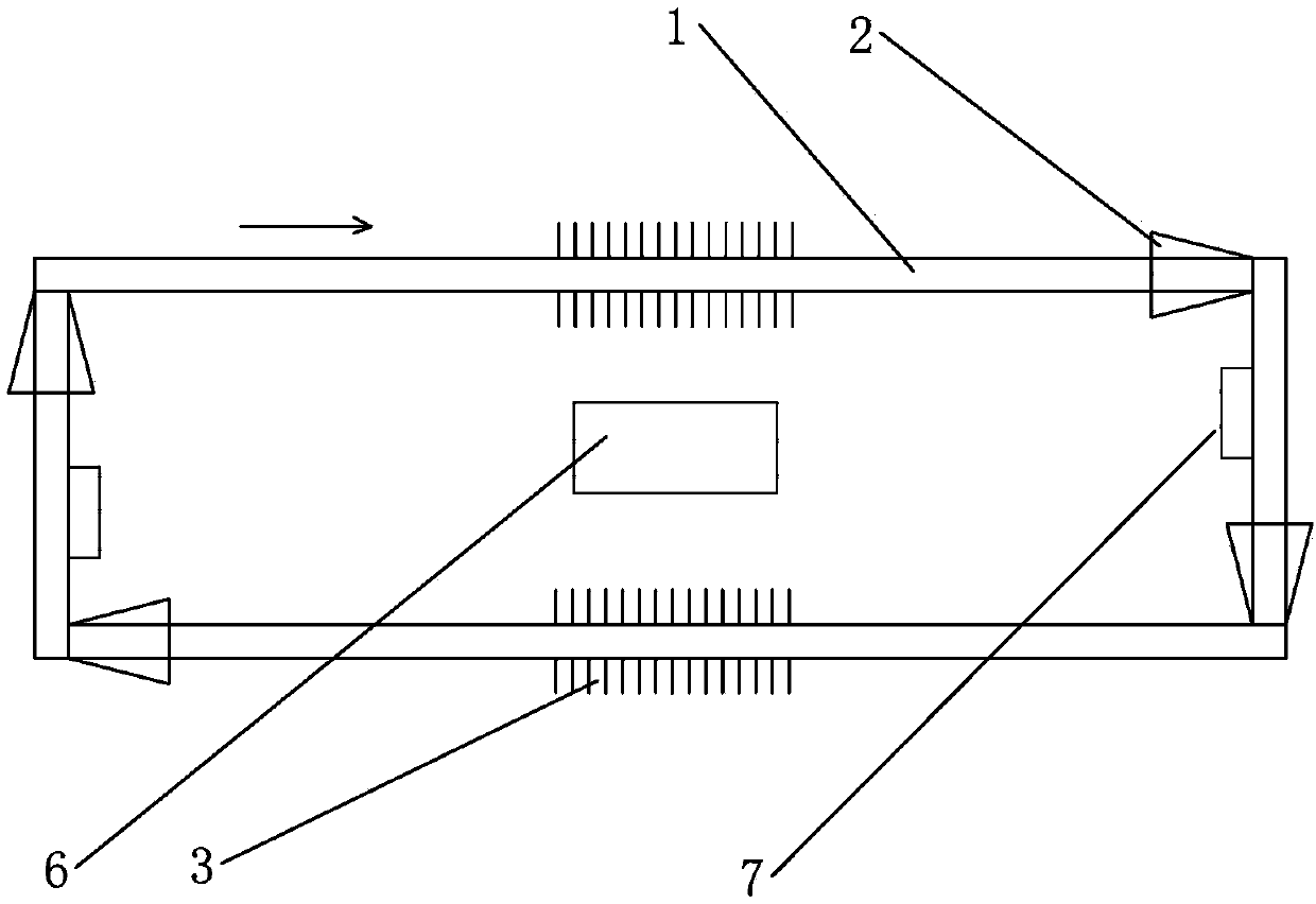
[0031] On the basis of the second embodiment, the difference from the second embodiment is that the heat dissipation section has no heat dissipation fins 4 but a Peltier heat dissipation device 7 . Peltier heat dissipation is also a heat dissipation method for electronic equipment that has been demonstrated and tested. However, when Peltier devices are used for heat dissipation, dew condensation may occur at the cold end, which will cause adverse effects on electronic equipment. In this embodiment, however, the Peltier heat sink 7 is an indirect auxiliary heat sink and is kept away from the electronic device, even if dew condensation occurs, it will not cause harm to the electronic device.
PUM
 Abstract
Description
Claims
Application Information