Composite balancing earth-pressure shielding machine

A technology of earth pressure balance and shield machine, which is applied in the direction of earth drilling, mining equipment, tunnels, etc., to achieve the effect of improving flow plastic performance

Active Publication Date: 2007-06-20
CHINA SHENHUA ENERGY CO LTD
View PDF0 Cites 31 Cited by
  • Summary
  • Abstract
  • Description
  • Claims
  • Application Information

AI Technical Summary

Problems solved by technology

[0005] The object of the present invention is to provide a compound earth pressure balance shield machine to solve the problem of normal excavation in highly permeab

Method used


Image

  • Composite balancing earth-pressure shielding machine
  • Composite balancing earth-pressure shielding machine
  • Composite balancing earth-pressure shielding machine

Examples


Embodiment Construction

[0023] The shield machine provided by the present invention will be further described below in conjunction with the accompanying drawings, but the present invention is not limited thereto.

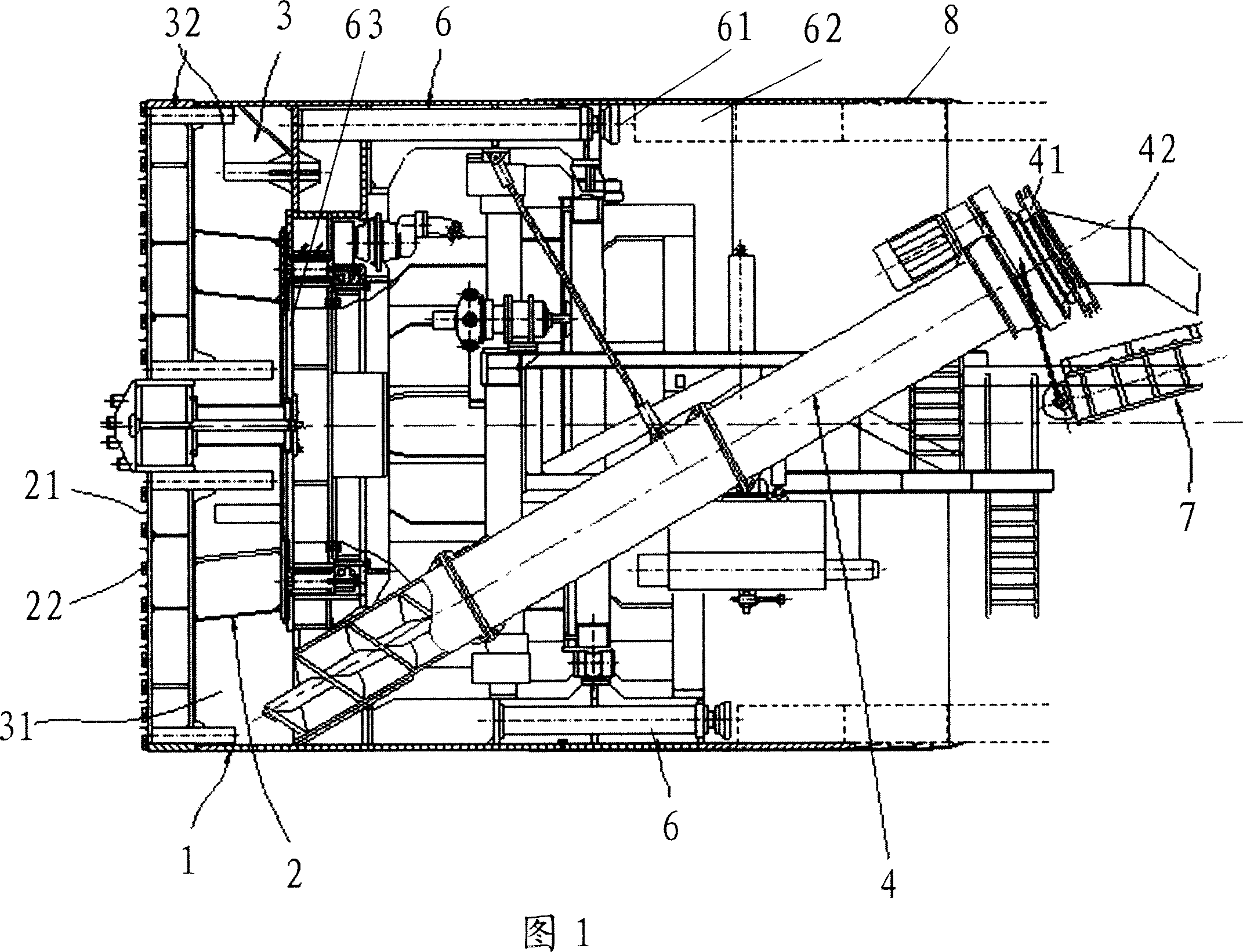
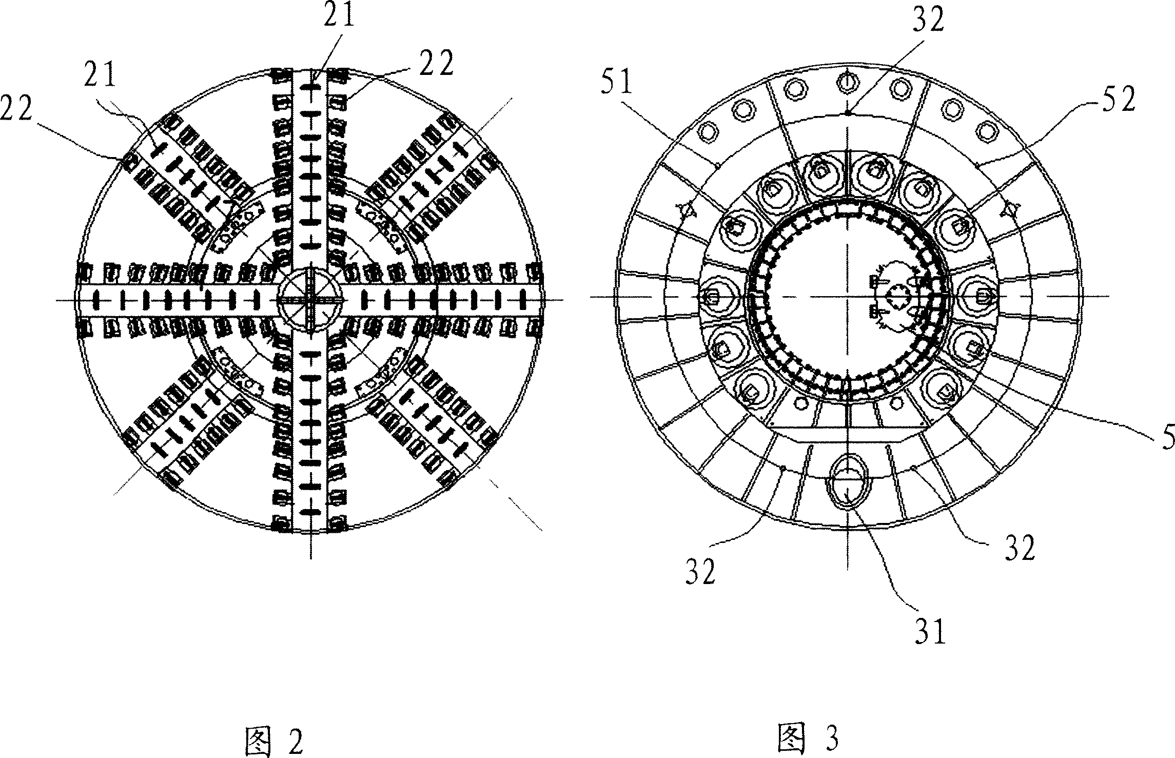
[0024] As shown in Figures 1 and 2, the composite earth pressure balance shield machine according to the present invention includes a casing 1, the front end of which is a cutter head 2; 22, where the blade edge of the cutting knife 22 is slightly behind the tearing knife 21. The tearing knife 21 is mainly aimed at unweathered block stones, such as unweathered tuff, by extruding and self-rolling, to break relatively hard block stones. Run into soft soil layer, tearing knife 21 loses its effect, this moment relies on cutting knife 22, under the rotation of cutterhead 2, cuts soft soil. The actual shield tunneling process is completed under the joint action of these two knives.

[0025] Referring to Fig. 1 and Fig. 3, the cutter head 2 rear portion is the soil bin 3, and the soil bin 3 bot...


PUM


Abstract

A composite soil pressure balance shield machine, comprising : shell (1), cutter head (2), soil storer (3), spiral conveyer (4) and impelling oil cylinder (6),it is characterized in that the said cutter head is set front of the shell, equipped with tearing knife (21) and the cutting knife (22), and the cutter point of the said cutting knife is a little back of the tearing knife; the soil storer is located rear the cutter head, and its wall surface is installed with injecting holes (32), the rear end is installed with pressure balancing equipment (5), and a soil outlet (31)is set under the soil storer; the inlet under the spiral conveyer connects the soil outlet of the container; the said impelling oil cylinder are uniformly installed along the shell inner wall. The shield machine solves the normal tunneling problem on sand or gravel eggs (gravel) layer of high water permeability, or the normal tunneling problem when it need to pass through more than 30 centimeters large stones and other obstructions.

Description

technical field [0001] The invention relates to a compound earth pressure balance shield machine, more specifically, a compound earth pressure balance shield machine suitable for high-permeability soil layers. Background technique [0002] For power plants built on riversides and seasides, circulating water intake is a very important project. In the past, open channels were basically used to extract water, but the construction is very difficult, especially for shallow water intake. Later, with the improvement of construction technology, construction techniques such as immersed pipe and pipe jacking were introduced, but there are still many disadvantages, especially the large-diameter water intake tunnel. [0003] With the introduction of the shield construction method, it has gradually replaced the previous construction technology. However, the geology of the circulating water intake tunnel of the Ninghai Power Plant Project is complex, with many soil layers and high water c...

Claims


Application Information

Patent Timeline
IPC IPC(8): E21D9/087
Inventor 胡重明曾宪江徐其宝张福民
Owner CHINA SHENHUA ENERGY CO LTD
Why Eureka
Try Eureka