X-ray manipulator

An x-ray, axial technology, applied in the field of x-ray manipulators, can solve problems affecting good edge definition, and achieve the effect of ensuring accuracy and precision

Active Publication Date: 2007-06-20
DAGE PRECISION INDS
View PDF0 Cites 7 Cited by
  • Summary
  • Abstract
  • Description
  • Claims
  • Application Information

AI Technical Summary

Problems solved by technology

However, at very small spots, motion within the x-ray setup can seriousl

Method used


Image

  • X-ray manipulator
  • X-ray manipulator
  • X-ray manipulator

Examples


Embodiment Construction

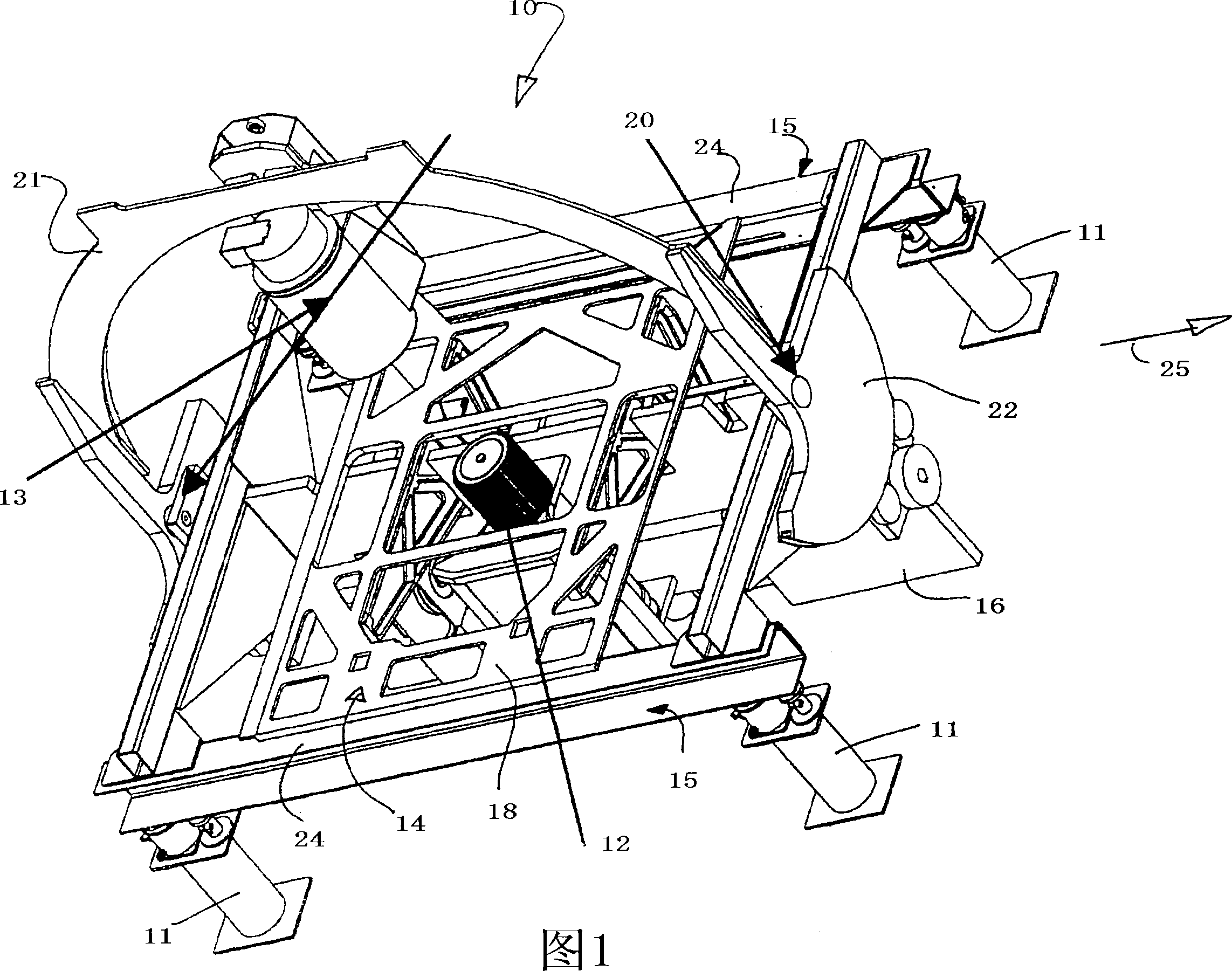
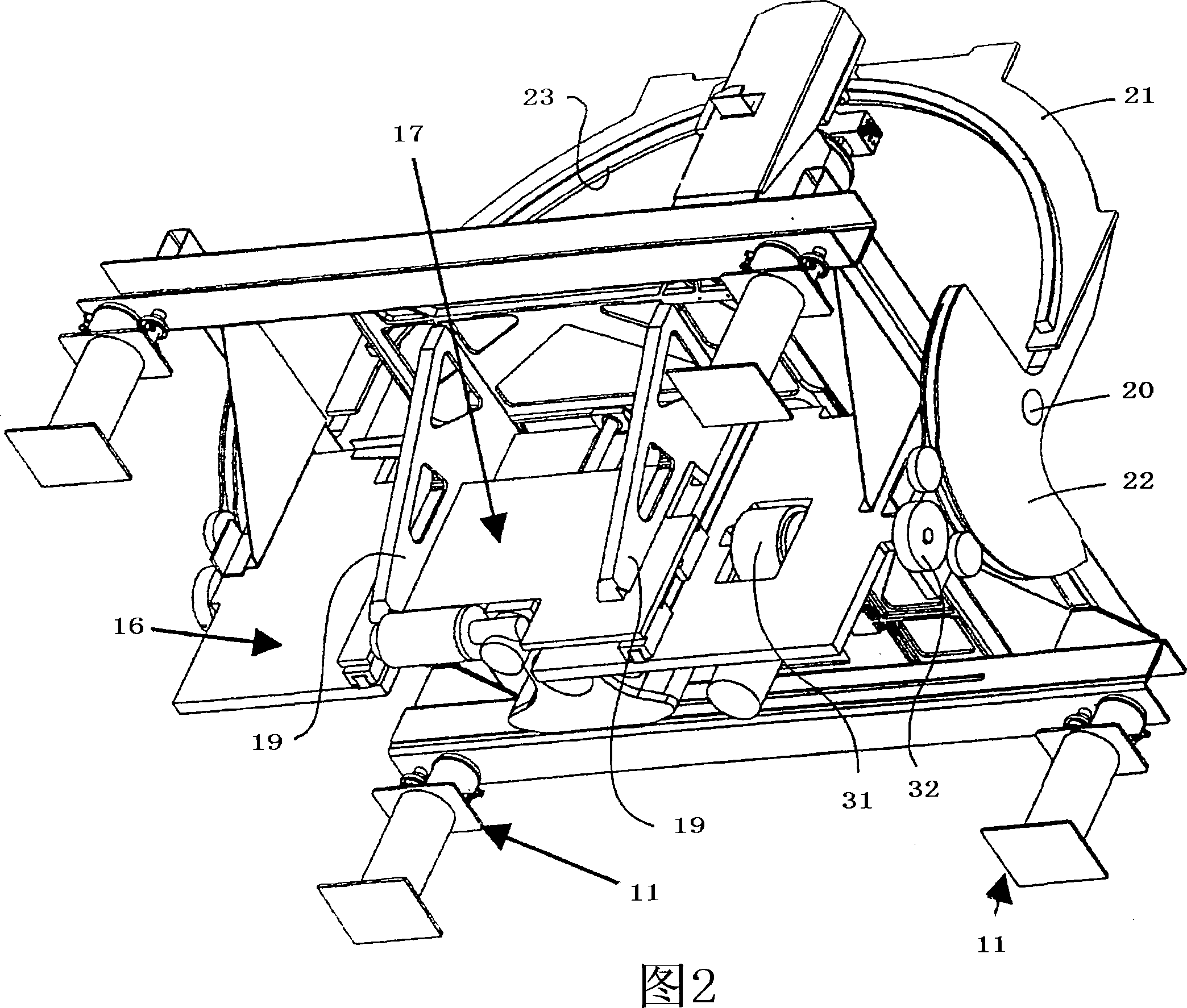
[0025] Referring to the drawings, the frame 10 is supported on feet 11 which are themselves mounted in a cabinet (not shown). The housing is of the usual type and forms a shield to protect the user from the harmful effects of x-rays. An x-ray tube 12 for generating x-rays and an x-ray detector 13 are installed on the frame. Between the tube 12 and the detector 13 there is a movable plate 14 adapted to support the object to be imaged.

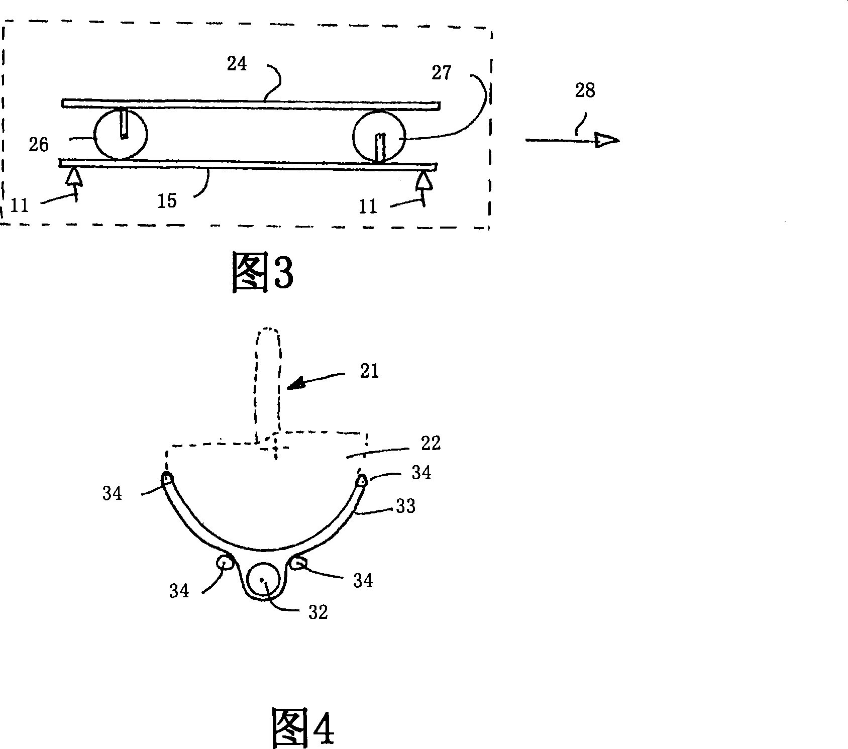
[0026] Each leg 11 includes an anti-vibration mount comprising self-leveling air bearings of known type. Pressurized air is supplied to the bearings and substantially isolates the frame from externally applied vibrations that may be transmitted to the enclosure.

[0027] The air bearings are paired and arranged at the corners of the rectangle. Each pair of bearings 11 supports a corresponding beam 15 on which the frame 10 is mounted.

[0028] The frame 10 comprises a main support plate 16 arranged between beams 15 in a substantially vertical...


PUM


Abstract

A frame (10) for an x-ray inspection device comprises a structural member (16) to which is pivoted an arcuate frame (21). An x-ray source (12) is in use mounted directly to the member (16), and an x-ray detector (13) is movable around the frame (21). A three axis sample support for items to be imaged is arranged between the source (12) and detector (13). The frame (10) of the invention is particularly rigid.

Description

technical field [0001] The present invention relates to an x-ray manipulator, in particular to a manipulator suitable for observing the internal structure of a micro electric device. Background technique [0002] X-rays are generated when the electron beam excites an appropriate target. As is known, certain materials absorb x-rays better than others, so the internal structure of the component can be imaged by a suitable x-ray detector. In particular, higher degrees of magnification are obtained by increasing the distance of the x-ray source from the detector relative to the distance of the x-ray source from the object being imaged. [0003] When imaging at higher magnifications, it is important to reduce the x-ray source to the smallest possible spot. Only in this way can the edge definition of the image be higher. However, at very small spots, motion within the x-ray device can seriously affect the possibility of obtaining good edge definition at higher magnifications. ...

Claims


Application Information

Patent Timeline
IPC IPC(8): G01N23/207
CPCG01N23/207
Inventor 本杰明·金斯莱·斯图尔特·皮科克
Owner DAGE PRECISION INDS
Why Eureka
Try Eureka