Hair clipper

A haircut pusher and hair clipper technology, which is applied in metal processing and other directions, can solve problems such as vibration of accessories, and achieve the effect of easy production management

Inactive Publication Date: 2007-06-27
MATSUSHITA ELECTRIC WORKS LTD
View PDF1 Cites 3 Cited by
  • Summary
  • Abstract
  • Description
  • Claims
  • Application Information

AI Technical Summary

Problems solved by technology

However, in this way unless the part of the attachment attached to the main body is precisely manufactured, the attachment will vibrate

Method used


Image

  • Hair clipper
  • Hair clipper
  • Hair clipper

Examples


Embodiment Construction

[0019] Hereinafter, embodiments of the present invention will be described with reference to the accompanying drawings.

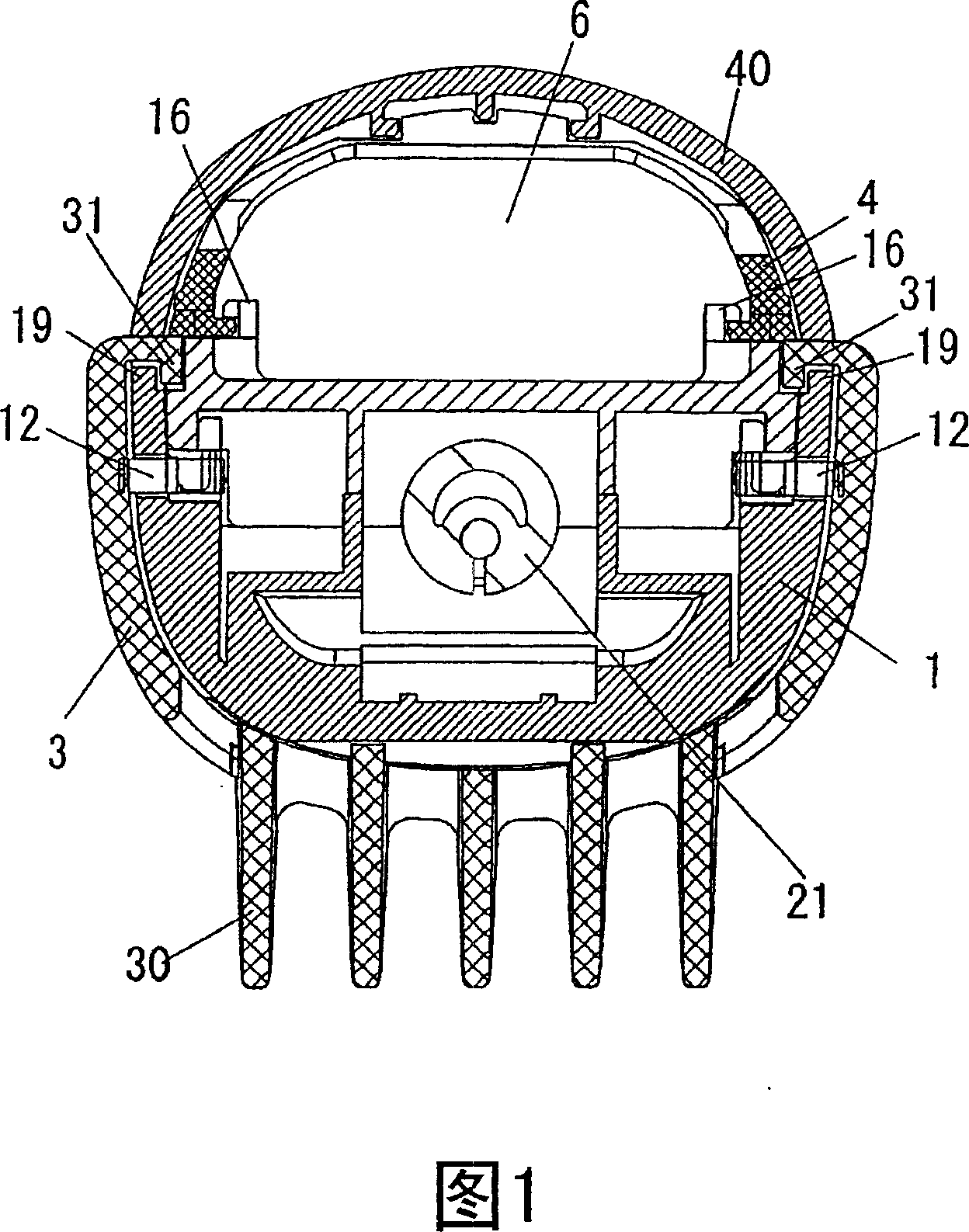
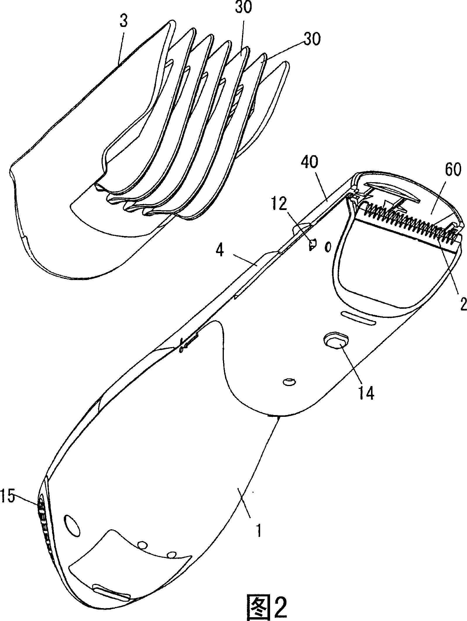
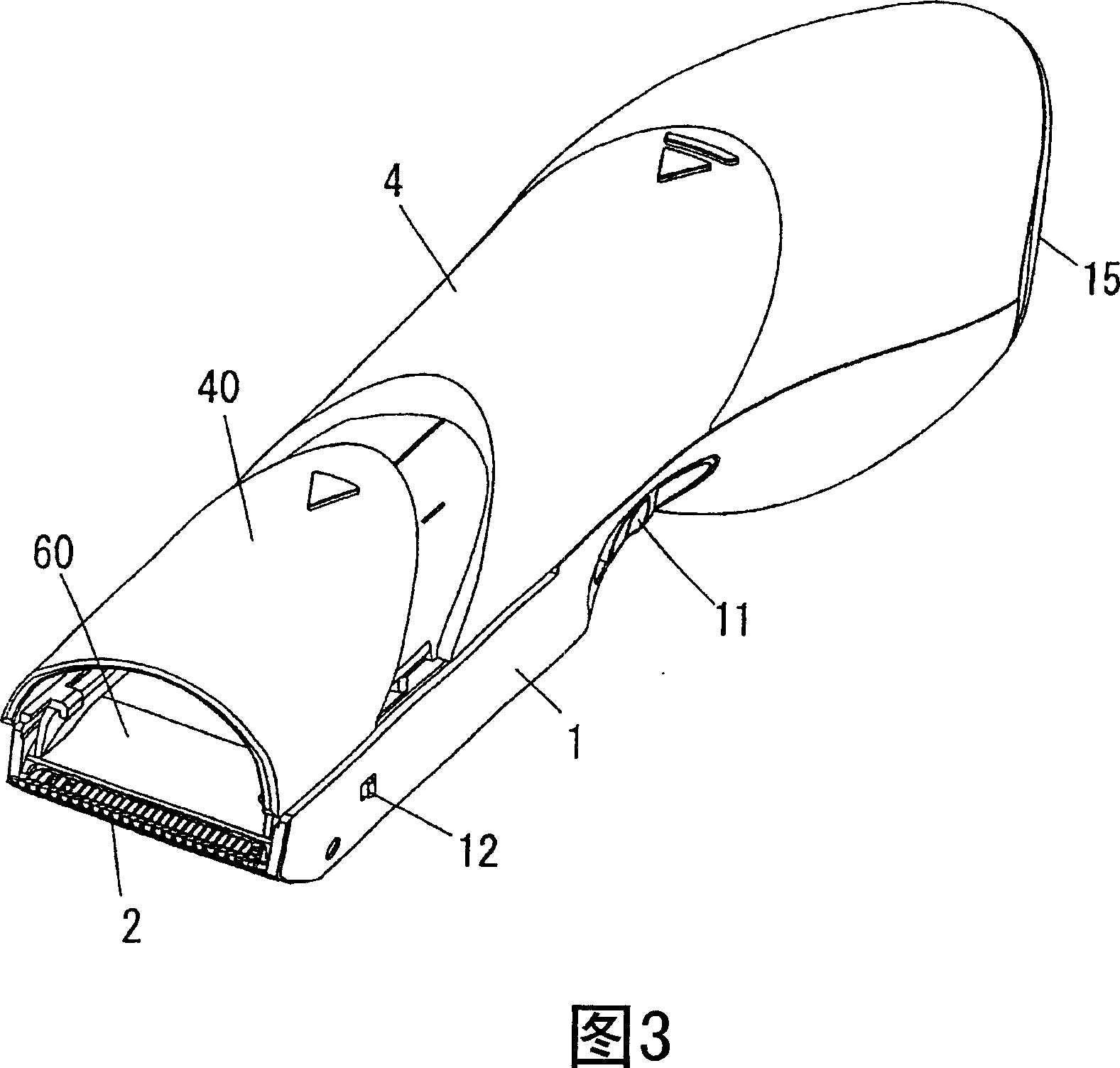
[0020] As shown in Figure 2, the hair clipper of the present invention comprises a main body 1 and an accessory 3 detachably connected to the main body 1, and a scissor part 2 comprising a comb-shaped fixed blade and a comb-shaped movable blade is provided at the front end of the main body 1 , Attachment 3 is used to adjust the cutting height. As shown in FIGS. 3 and 4 , the hair clipper further includes a top cover 4 detachably attached to the top surface of the front of the main body 1 . A suction fan 5 and an electric motor 50 driving the suction fan 5 are accommodated at the rear of the main body 1 . An electric motor 20 is accommodated at the front of the main body 1 for reciprocatingly driving the movable blades of the scissors part 2 .

[0021] The top cover 4 serves to define a suction channel 6 between the top surface of the main body 1 and itsel...


PUM


Abstract

A hair clipper includes a body of the cutting hair knife part provided in the front end, and accessories for adjusting cutting height which can dismantle and slide and be mounted on the body. The accessories have cross section with ''U'' shape in essence suitable for covering the bottom of the body. In addition, the accessories include hook-shape portions respectively formed on the opposite topside of the accessories to definite the slot opening downwards. The body has guiding ribs mounting in in the slots of the accessories for guiding the accessories to slide. The body includes spring elements poisoned on the opposite sides respectively for pressing outwards the inner side surface of the accessories.

Description

technical field [0001] The present invention relates to hair clippers, and more particularly, to hair clippers having an attachment to adjust the height of the hair cut. Background technique [0002] As hair clippers, there is traditionally provided a type of hair clipper in which the attachment has a comb portion mounted on the clipper body in contact with the scalp so that the distance between the clipper portion and the scalp is limited by the attachment to adjust the cutting height. [0003] In a hair clipper including an accessory, the accessory is slidably connected to the main body such that the cutting height is changed by sliding the accessory so that the cutting height can be adjusted by sliding a single accessory. In such a hair clipper, the attachment is formed as a tubular cap on top of the main body to avoid any vibration thereof relative to the main body (see, for example, Japanese Patent Laid-Open Application No. 2005-73933). [0004] However, if the suctio...

Claims


Application Information

Patent Timeline
IPC IPC(8): B26B19/20B26B19/42B26B19/44
CPCB26B19/20B26B19/44
Inventor 益子佳典小川仁志侧垣智
Owner MATSUSHITA ELECTRIC WORKS LTD
Why Eureka
Try Eureka