
Eureka
For R&D, Eureka makes reading and utilizing patents & technical documents easy.
Eureka AIR
Designed for self-driven R&D workflows. Generate viable solutions, solve complex R&D challenges, empower your innovation with AI.

Eureka Materials
Designed for material experts only. Revolutionize your material R&D, from search, analyze, to developing new materials.

TechResearch
Generate reliable direction feasibility study reports for your R&D in just a few steps.

TechSeek
Discover and master advanced knowledge NOW. Basics, ideas, possibilities, all at once.

TechMind
As an expert in R&D Theories, TechMind can generates customized viable solutions instantly.

TechRisk
Analyze your overall solution with one click, know your potential R&D risks in advance.

TechMonitor
Get weekly tech updates, stay abreast of the latest tech innovations and key insights.
Multifunction building form frame module
It is a multi-functional and architectural technology, which is applied in the field of construction, construction component preparation and building construction, etc. It can solve the problems of unbalanced force on the left and right sides of the flat wings, achieve rapid installation and disassembly, reduce production costs, The effect of reducing labor intensity
- Summary
- Abstract
- Description
- Claims
- Application Information
AI Technical Summary
Problems solved by technology
Method used
Image


Examples
Embodiment 1
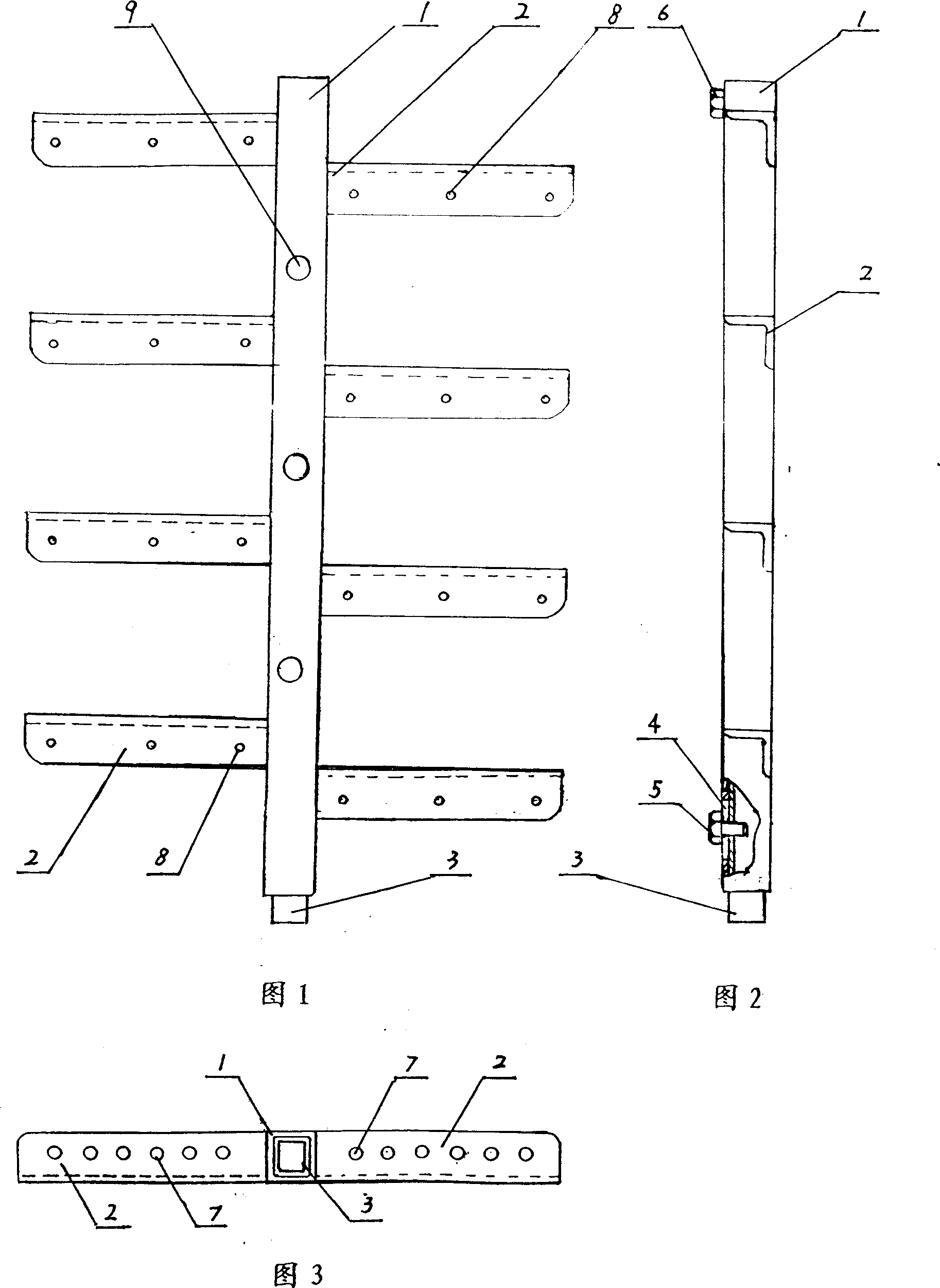
[0022] Embodiment 1: One of a kind of multifunctional architectural formwork components, a single formwork.
[0023] Referring to Fig. 1, Fig. 2 and Fig. 3, process 3 first distance screw holes 9 above the first square pipe 1, and make the central positions and apertures of each first distance screw holes the same, in the first square pipe The bottom of the bottom is also provided with the corresponding first distance screw hole; the first strip hole 4 is processed on the side of one end of the first square tube 1, and the first connecting screw 5 passes through the first strip hole and one end of the first square tube. Connect the first connector 3 inside; Weld a first stop screw cap 6 on the other end of the same side of the first square tube;
[0024] Be provided with a row of first connecting holes 7 on the side perpendicular to the side of the side of the "L"-shaped flat wing and the first square tube in each section, the central position, aperture and hole spacing of the...
Embodiment 2
[0025] Embodiment 2: Referring to Fig. 4, on the basis of Embodiment 1, more than 2 first spare distance screw holes are processed on the side where each flat wing 2 of the single formwork is flush with the top of the first square tube 1 10, which constitutes one of the multifunctional architectural formwork components, another form of single formwork.
Embodiment 3
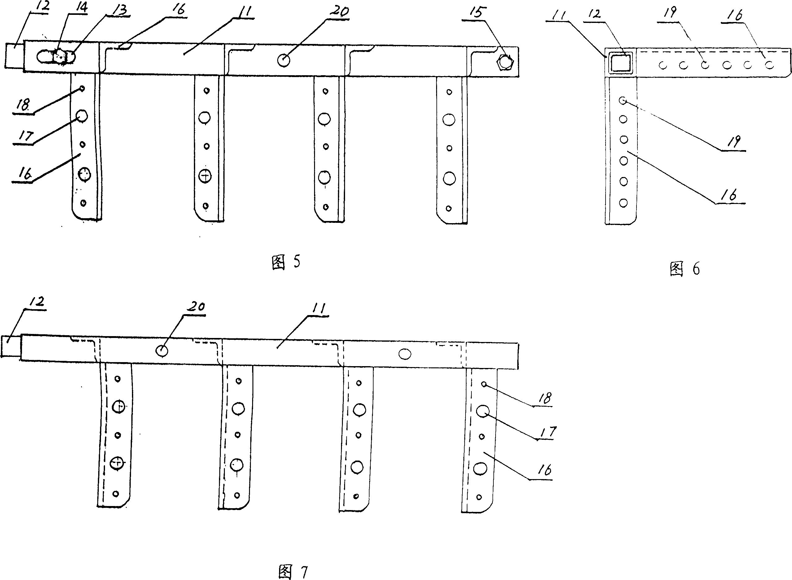
[0026] Embodiment 3: The second of a multi-functional building formwork assembly, internal corner formwork.
[0027] Referring to Fig. 5, Fig. 6 and Fig. 7, the second bar-shaped hole 13 is processed on one side of the second square tube 11, and the corresponding second distance screw is processed on the two parallel faces of the second square tube 11 of the female corner formwork Holes 20; the second connecting screw 14 passes through the second bar-shaped hole 13 and is connected with the second connector 12 installed in the end of the second square pipe 11, and the second stop screw cap 15 is welded on the other end of the second square pipe. on the same side;
[0028] Process two second standby distance screw holes 17 and three second self-tapping screw holes 18 on the side where the female corner wing of " L " shape is flush with the second square tube in each section; Process a row of second connection holes 19 on the other side of the corner wing, and make the center p...
PUM
 Abstract
Description
Claims
Application Information
 - R&D Engineer
- R&D Manager
- IP Professional
- Industry Leading Data Capabilities
- Powerful AI technology
- Patent DNA Extraction
Browse by: Latest US Patents, China's latest patents, Technical Efficacy Thesaurus, Application Domain, Technology Topic, Popular Technical Reports.
© 2024 PatSnap. All rights reserved.Legal|Privacy policy|Modern Slavery Act Transparency Statement|Sitemap|About US| Contact US: help@patsnap.com