Controller for electric vehicle charging system

A control device and charging system technology, which is applied to battery circuit devices, electric vehicles, circuit devices, etc., can solve the problems of small sensing distance, easy to generate interference, and difficult to install, so as to improve safety, avoid surrounding metal interference, and easily The effect of installation

Inactive Publication Date: 2007-06-27
BYD CO LTD
0 Cites 2 Cited by

AI-Extracted Technical Summary

Problems solved by technology

[0007] The present invention aims at the disadvantages of the control device of the above-mentioned electric vehicle charging system, such as large volume, difficult installation, small sensing distance, and ...

Method used

Described control device can also comprise current-limiting resistor 4, and described current-limiting resistor 4 is connected in series between power positive pole and control signal output terminal 5, is used for limiting the electric current flowing through magnetic induction switch 2 and light-emitting diod...

Abstract

This invention provides a control device for an electromotor charge system including a connection plug, a supply and an output end of a control signal, in which, said connection plug includes two parts interplugged to each other, the output of the control signal is connected with the positive of the supply, the first part of the plug includes a magnet, the second part includes a magnetic induction switch to compose a loop with the supply when it is closed.

Application Domain

Technology Topic

Image

  • Controller for electric vehicle charging system

Examples

  • Experimental program(1)

Example Embodiment

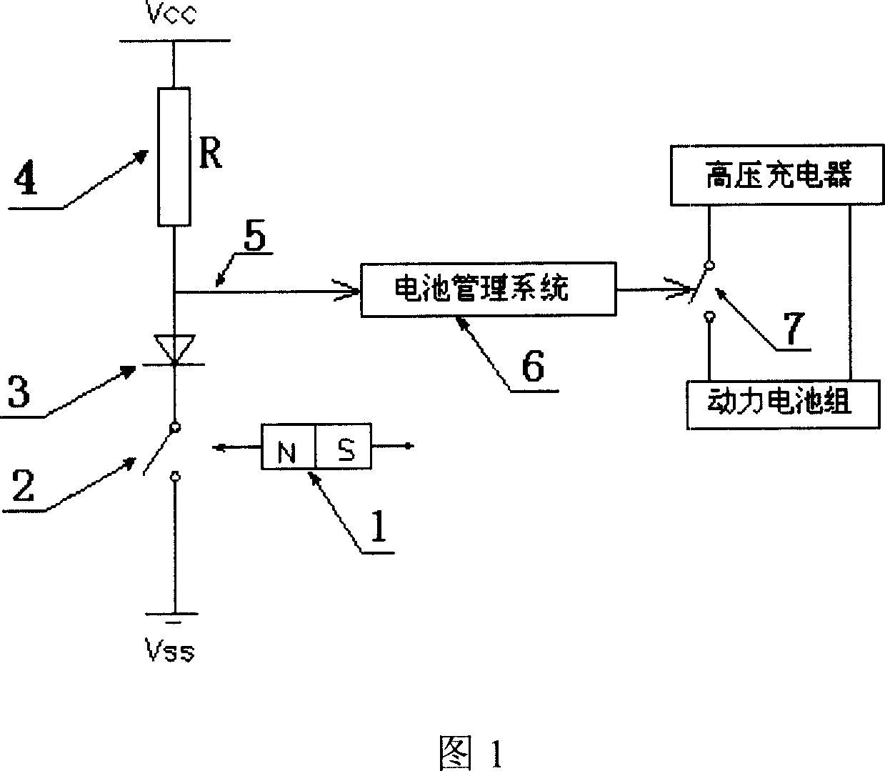
[0011] The device provided by the present invention will be further described below in conjunction with the accompanying drawings.
[0012] As shown in Figure 1, the control device of the electric vehicle charging system provided by the present invention includes a connecting plug (not shown), a power supply (not shown), and a control signal output terminal 5. The connecting plug includes two parts, two parts The control signal output terminal 5 is electrically connected to the positive pole of the power supply, wherein the first part of the connecting plug includes a magnet 1, and the second part includes a magnetic induction switch 2. When the magnetic induction switch 2 is closed, it forms with the power supply Loop.
[0013] Wherein, the magnet 1 can be any shape and any kind of magnet, preferably a permanent magnet.
[0014] The magnetic induction switch 2 can be any magnetic induction switch, preferably an embedded magnetic induction switch. When the magnet 1 approaches the magnetic induction switch 2, the magnetic induction switch 2 is electrocuted under the action of the magnetic field, and the current provided by the power supply passes through the magnetic induction switch 2, and the magnetic induction switch 2 and the power supply form a closed loop.
[0015] The connecting plug can be of any shape, and the material is any insulating material, such as one or more of insulating rubber, plastic, and resin. It is wrapped around the magnet 1 and the magnetic induction switch 2 to avoid electrical conduction during use. Among them, the first part including the magnet 1 is the charger end of the connection plug, and the second part including the magnetic induction switch 2 is the electric vehicle end of the connection plug. The connection plug also includes a charging interface. When the connection plug is inserted, the magnetic induction switch 2 is connected to the electric vehicle end. The switch 2 is closed and sends a control signal, which means that the connecting plug is plugged in and charging can be performed. The charging interface is well-known to those in the art and does not belong to the main content of the present invention, and will not be described here.
[0016] The movable plug-in manner between the two parts of the connecting plug is any plug-in manner known to those skilled in the art, and may be a direct contact type, an electromagnetic wave induction type, and the like.
[0017] The power supply is a DC power supply, which can be a separate additional power supply for the control device, or it can be and preferably is the battery of an electric vehicle, as shown in Figure 1, where Vcc is the positive electrode of the battery of the electric vehicle, and the voltage is 12 volts. Vss is ground.
[0018] The control signal output terminal 5 can be any conductive wire, which is electrically connected to the positive electrode of the power source, and the other end is electrically connected to the battery management system 6 for transmitting the control signal to the battery management system 6. When the magnetic induction switch 2 is not closed, the control signal output terminal 5 is at a high potential because it is electrically connected to the positive pole of the power supply; and when the magnetic induction switch 2 is closed, the control signal output terminal 5 is connected to the negative pole of the power supply through the magnetic induction switch 2, and is at a high potential. It becomes a low potential, so the potential has a falling edge, and the power supply supplies power to the battery management system 6 through the control signal output terminal 5, so that the control signal is obtained.
[0019] The control device may also include an indicating device 3, which is connected in series in the current loop formed by the power supply and the magnetic induction switch 2 for indicating the current working state of the electric vehicle. The indicating device 3 is preferably a light-emitting diode, which is forwardly connected to the current loop formed by the power supply and the magnetic induction switch 1. When the magnetic induction switch 2 is closed, the light-emitting diode lights up, indicating that the electric vehicle is currently in a chargeable state When the magnetic induction switch 2 is turned off, the light-emitting diode is off, indicating that the electric vehicle is currently in a non-charging state.
[0020] The control device may also include a current-limiting resistor 4 connected in series between the positive electrode of the power supply and the control signal output terminal 5 to limit the current flowing through the magnetic induction switch 2 and the light-emitting diode, and prevent the magnetic induction switch 2 and The light-emitting diode is damaged. The resistance value of the current-limiting resistor 4 is selected according to the maximum current of the magnetic induction switch 2 and the light emitting diode, and the selection of the resistance value is well known to those in the art.
[0021] The working process of the control device of the electric vehicle charging system shown in Fig. 1 is as follows: when the electric vehicle needs to be charged, the two parts of the connecting plug are plugged together, that is, the charger end (that is, the first part) of the connecting plug is connected to the connecting plug The electric vehicle end (that is, the second part) is plugged in, the magnetic induction switch 2 is closed, the loop is turned on, and the light-emitting diode turns on. At this time, the potential of the control signal output terminal 5 changes from the high potential (12v) when the loop is disconnected to low At a potential (0v), the battery of the electric vehicle supplies power to the battery management system 6 to send a control signal to the battery management system 6. The battery management system 6 starts to work to check whether the voltage of each power battery is normal. If it is normal, a charging control signal is sent to the charging contactor 7, the charging contactor 7 is closed, and the high-voltage charger starts to charge the power battery pack. When the charging is over, disconnect the plug, the magnetic induction switch 2 is disconnected due to the loss of the external magnetic field, the potential of the control signal terminal 5 changes from low potential (0v) to high potential (12v) again, and the power supply stops supplying power to the battery management system 6. Therefore, the battery management system 6 loses the control signal, the charging contactor 7 is disconnected, and the high-voltage charger stops charging.

PUM

no PUM

Description & Claims & Application Information

We can also present the details of the Description, Claims and Application information to help users get a comprehensive understanding of the technical details of the patent, such as background art, summary of invention, brief description of drawings, description of embodiments, and other original content. On the other hand, users can also determine the specific scope of protection of the technology through the list of claims; as well as understand the changes in the life cycle of the technology with the presentation of the patent timeline. Login to view more.

Similar technology patents

Strapping inertial navigation gyroscope clinometer based on MEMS device

InactiveCN101493008ARealize measurement while drillingReduce volumeSurveyTurn-sensitive devicesSpeed measurementContinuous measurement
Owner:BEIJING LIUHE GREATNESS TECH

Classification and recommendation of technical efficacy words

  • Easy installation
  • Reduce volume

Implant release mechanism

ActiveUS20080140178A1Reduce volumeReduce outer diameterStentsOcculdersDilatorStent
Owner:COOK MEDICAL TECH LLC

Flash storage chip and flash array storage system

ActiveUS20080052451A1Reduce volumeImprove data transmission rateMemory adressing/allocation/relocationData transmissionPCI Express
Owner:PHISON ELECTRONICS

Devices and methods for placement of partitions within a hollow body organ

InactiveUS20070167960A1Reduce volumeSuture equipmentsStapling toolsTissue acquisitionBody organs
Owner:ETHICON ENDO SURGERY INC
Why Eureka
Try Eureka