Oil supply device

A technology of oil supply device and synchronous device, which is applied to transmission parts, couplings, mechanical drive clutches, etc., and can solve problems such as failure to supply oil

Inactive Publication Date: 2007-06-27
ZF FRIEDRICHSHAFEN AG
View PDF4 Cites 6 Cited by
  • Summary
  • Abstract
  • Description
  • Claims
  • Application Information

AI Technical Summary

Problems solved by technology

But the mechanism used to direct the injected oil doesn't provide better oil supply to the multitude of parts in the car's transmission

Method used


Image

  • Oil supply device
  • Oil supply device

Examples


Embodiment Construction

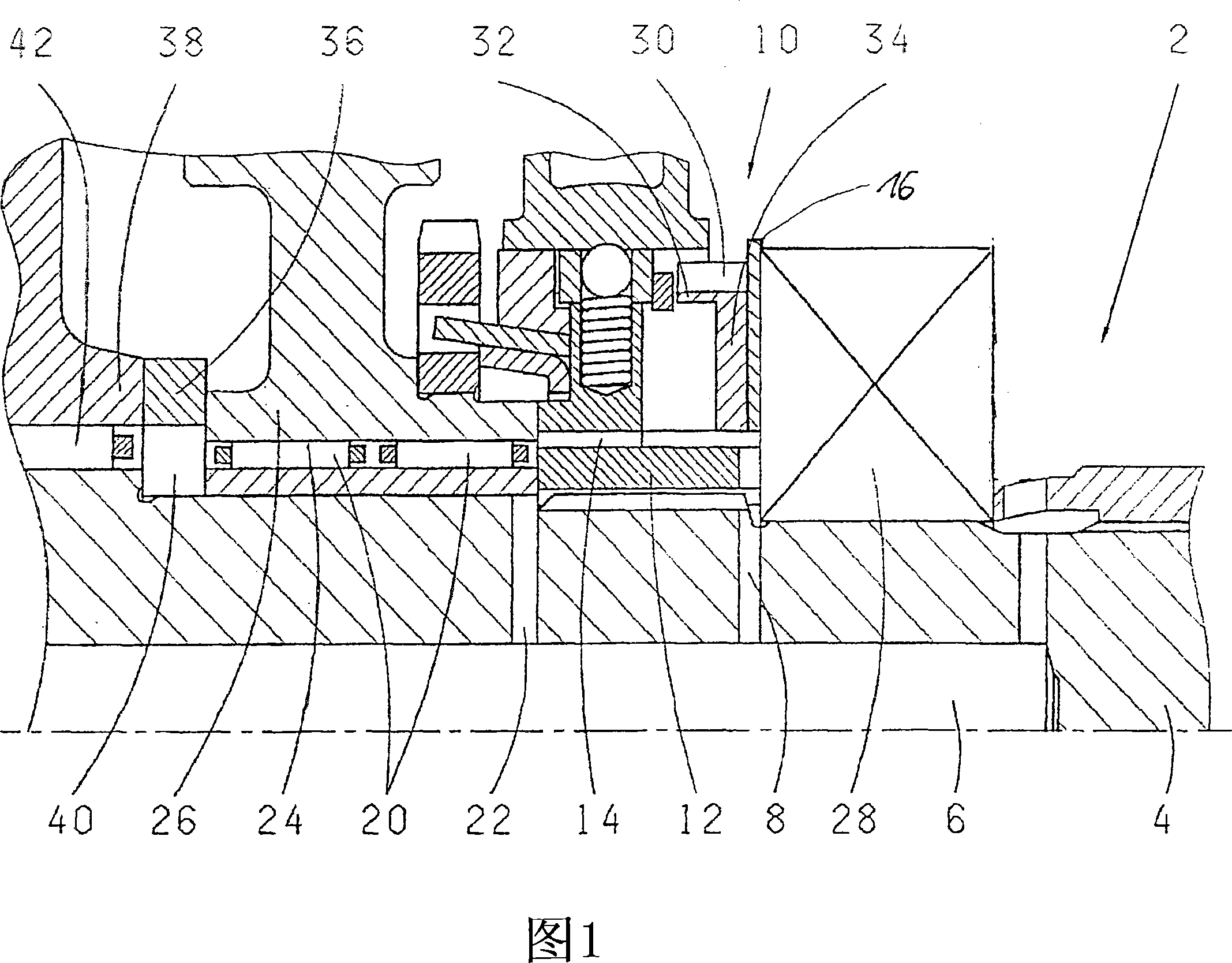
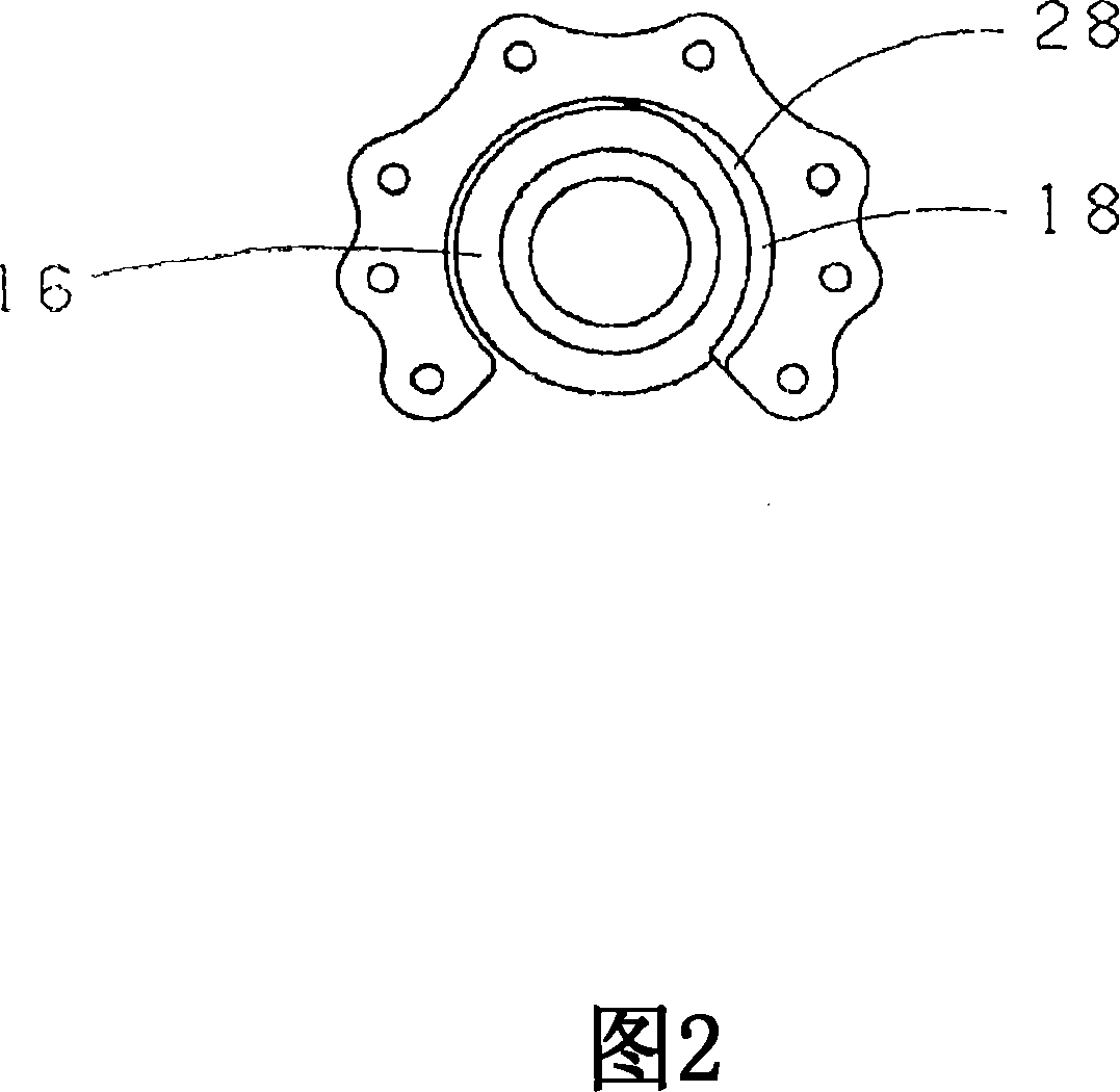
[0014] FIG. 1 shows a partial sectional view of a motor vehicle transmission 2 according to the invention having a shaft 4 with an axially central bore 6 . The oil enters the synchronizer 10 through the transverse bore 8 . The synchronizing body of the synchronizing device 10 has a bore 14 , through which and a fixing plate 16 with a sickle-shaped opening 18 , the volume of oil flowing in the rotational movement and in the direction of rotation is reduced between the synchronizing device 10 and the bearing 28 . Part of the volume flow of the oil flows via the central bore 6 on the shaft 4 , the transverse bore 8 and the bore 14 in the synchronizing body 12 to the parts to be supplied with oil, here for example the bearing 20 . The remaining oil can escape radially as a loss between the synchronizer 10 and the bearing 20 . Additional oil can be supplied to the running surface 24 of the gear wheel 26 via the transverse bore 22 . Synchronizing body 12 has, on the side facing be...


PUM


Abstract

The invention relates to an oil supply device for a vehicle transmission (2) with: toothed wheels mounted on shafts; bearing arrangements inside of which toothed wheels and shafts are rotationally mounted, and; synchronizing devices (10), which are moved into the desired shifting positions via gear shift rods and gear shift forks by actuating a gear shift lever. One shaft (4) has an axially extending central hole (6) and at least one cross hole (8) for supplying oil. The oil supply device has holes (14) in a synchronizing body (12) of the synchronizing device (10), and a fixing plate (16) with a sickle-shaped cavity (18).

Description

technical field [0001] The invention relates to an oil supply device whose features are specified in the preamble of claim 1 . Background technique [0002] In motor vehicle transmissions, especially manual transmissions, the oil supply of gears, shafts and floating wheel bearings on and in the shafts is of particular importance due to the complex design of the motor vehicle transmission. On the one hand, the oil supply to the gears and bearings must be sufficient, and on the other hand, the smallest possible oil supply must be used to ensure a small traction torque in order to achieve good shift performance, which is especially important for shift comfort in manual transmissions. big impact. Similarly, the oil temperature should be kept moderate, and the oil supply of the reverse gear and the cold shift performance of the transmission must be ensured. In order to solve the problems related to this, various types of oil pumps, hollow shafts and oil pipes are used, or in au...

Claims


Application Information

Patent Timeline
Patent Type & Authority Applications(China)
IPC IPC(8): F16N7/18F16N7/22F16H57/04
CPCF16H57/043F16D23/04F16H57/0471F16D2023/0681F16H57/0473F16H57/0427F16D2300/06F16H57/0409
Inventor 哈拉尔德·克洛泽
Owner ZF FRIEDRICHSHAFEN AG
Why Eureka
Try Eureka