
Improved vacuum pump

A vacuum pump and pump body technology, which is applied to pumps, parts of pumping devices for elastic fluids, pump components, etc., can solve the problems of small and stable vacuum performance, low work efficiency, and high cost, and achieve reliable and stable vacuum performance. Easy installation, disassembly and maintenance, high work efficiency

Inactive Publication Date: 2013-08-14
NANTONG LONGYING VACUUM PUMP
View PDF0 Cites 0 Cited by
  • Summary
  • Abstract
  • Description
  • Claims
  • Application Information

AI Technical Summary

Problems solved by technology

The vacuum pumps in the prior art have disadvantages such as complex structure, small and stable vacuum performance, low working efficiency, high cost, easy rusting of the rotor, resulting in non-operation, and inconvenient installation and maintenance.

Method used


Image

  • Improved vacuum pump

Examples


Embodiment Construction

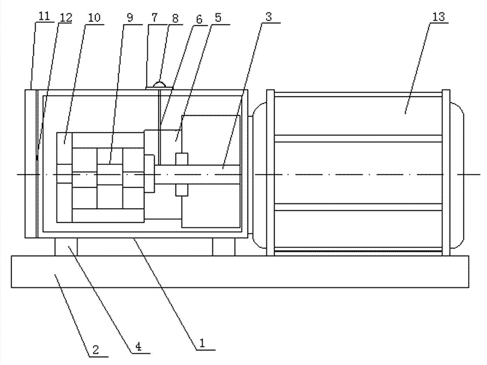
[0014] Such as figure 1 As shown, an improved vacuum pump of the present invention includes a pump body 1, the pump body 1 is fixed on the machine base 2, a first-stage rotor 3 is arranged inside the pump body 1, and one end of the first-stage rotor 3 is connected to a The motor 13 at one end of the pump body 1, the motor 13 is also fixed on the machine base 2, a buffer pad 4 is provided between the pump body 1 and the machine base 2, and a motor 13 is provided at the end of the first-stage rotor 3 away from the motor 13. The first-stage top cover 5, the top of the first-stage rotor 3 is connected to the bottom of the oil delivery pipe 6 that runs through the first-stage top cover 5, the top of the oil delivery pipe 6 is set on the top of the pump body 1, and the pump body 1 is located at the top of the oil delivery pipe 6. Oil end cover 7, the oil delivery end cover 7 is provided with an end cover handle 8, the other end of the first-stage rotor 3 is connected to the second-s...


PUM


Abstract

The invention discloses an improved vacuum pump, comprising a pump body. The improved vacuum pump is characterized in that the pump body is fixed on a machine base; a first-level rotor is arranged in the pump body; one end of the first-level rotor is connected with a motor arranged on one end of the pump body; the motor is also fixed on the machine base; one end of the first-level rotor, which is far away from the motor, is provided with a first-level top cover; the top of the first-level rotor is connected with the bottom of an oil transportation pipe penetrating through the first-level top cover; the top of the oil transportation pipe is arranged on the top of the pump body; the other end of the first-level rotor is connected with a second-level rotor; one end of the second-level rotor, which is far away from the motor, is provided with a second-level top cover; the outer side of the pump body, which is far away from the motor, is provided with an end cover matched with the pump body; the pump body is provided with an oil transportation end cover on the top position of the oil transportation pipe; the oil transportation end cover is provided with an end cover handle; and a buffer cushion is arranged between the pump body and the machine base. The improved vacuum pump has the advantages of simple structure, reliable and stable vacuum performance, convenience for rotor oil supply, low cost, high work efficiency and convenience for installation, disassembly and maintenance.

Description

technical field [0001] The invention relates to the field of pumps, in particular to an improved vacuum pump. Background technique [0002] The vacuum pump is a rotary variable displacement vacuum pump. It can be used in a wide pressure range with a backing pump. It has a large pumping speed and is insensitive to dust and water vapor in the pumped gas. Vacuum pumps are widely used in plastic machinery, pesticide chemical industry, dye chemical industry, brick and tile machinery, low temperature equipment, papermaking machinery, pharmaceutical chemical industry, food machinery, industrial electric furnace, electronics industry, vacuum equipment, chemical fertilizer, metallurgy, petroleum, mining, foundation treatment and other fields . The vacuum pumps in the prior art have disadvantages such as complex structure, small and stable vacuum performance, low working efficiency, high cost, easy rusting of the rotor, resulting in non-operation, and inconvenient installation and ma...

Claims


Application Information

Patent Timeline
Patent Type & Authority Applications(China)
IPC IPC(8): F04C25/02F04C29/00
Inventor 樊忠
Owner NANTONG LONGYING VACUUM PUMP
Learn More