
Superconducting cable line

A technology of superconducting cables and lines, applied in superconducting devices, circuits, superconducting/high-conducting conductors, etc., which can solve problems such as differences and large heat

Inactive Publication Date: 2007-06-27
SUMITOMO ELECTRIC IND LTD
View PDF2 Cites 13 Cited by
  • Summary
  • Abstract
  • Description
  • Claims
  • Application Information

AI Technical Summary

Problems solved by technology

Although the cooling system can be used to cool down to an appropriate temperature so that hydrogen can be maintained in a liquid state, however, since liquid hydrogen has a low-temperature boiling point of about 20K, which is significantly different from the normal temperature of the environment, the heat intruded from the outside becomes very large

Method used


Image

  • Superconducting cable line
  • Superconducting cable line
  • Superconducting cable line

Examples


example 1

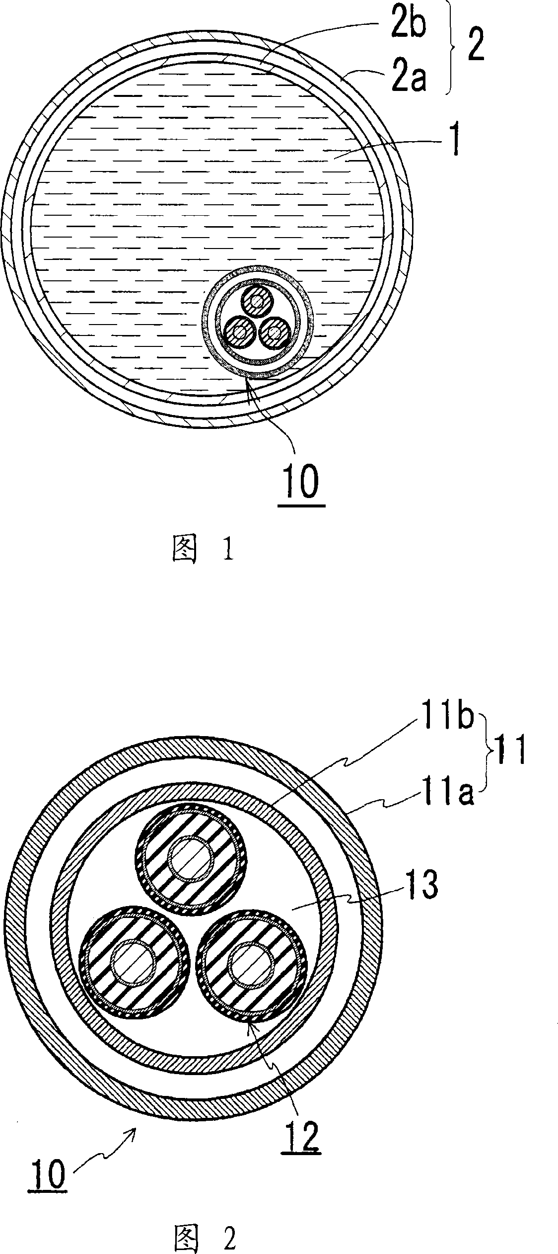
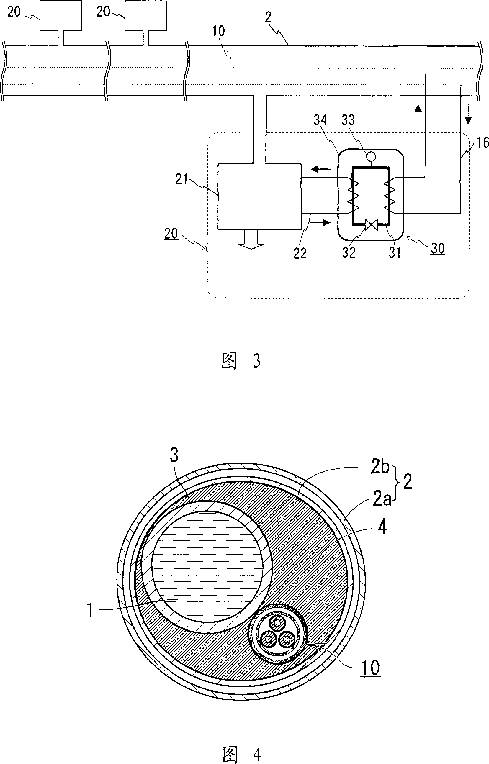
[0051] Fig. 1 is a schematic cross-sectional view of the structure of a superconducting cable line of the present invention. Fig. 2 is a schematic cross-sectional view of the structure of a portion near the superconducting cable in the superconducting cable of the present invention. Fig. 3 is a schematic diagram of a structure in which the conductive cabling of the present invention is constructed. The same characters in the drawings indicate the same parts. The superconducting cable of the present invention includes a heat insulating pipe 2 for fluid used to transport liquid hydrogen 1, a superconducting cable 10 housed in the heat insulating pipe 2 for fluid, and a cable for regulating the temperature of liquid hydrogen 1 The temperature of the coolant in the heat exchange device 30.

[0052] The superconducting cable 10 used in this example has a structure in which three cable cores 12 are twisted and housed in a heat insulating tube 11 for the cable, and its structure is...

example 2

[0059] Although the superconducting cable is immersed in liquid hydrogen in the above-mentioned Example 1, the superconducting cable may be housed in a heat insulating pipe for fluid without being immersed in liquid hydrogen. As an example, a delivery channel for liquid hydrogen may be provided separately in a thermally insulating tube for fluid. Fig. 4 is a schematic diagram of the structure of the superconducting cable of the present invention, which includes a delivery tube for liquid hydrogen and a heat exchanger partition inside the thermal insulation tube for fluid, which is a schematic horizontal view of the structure near the cable Sectional view. The superconducting cable has a structure including a separate delivery tube 3 for delivery of liquid hydrogen in the inner tube 2b of the heat insulating tube 2 for fluid. The heat exchanger partition plate 4 having high thermal conductivity is provided in a space surrounded by the inner periphery of the inner pipe 2b, the ...


PUM

PropertyMeasurementUnit
Resistivityaaaaaaaaaa
Dielectric constantaaaaaaaaaa

Abstract

A superconductive cable line, comprising an insulating pipe (2) for fluid through which a liquid hydrogen (1) is carried, a superconductive cable (10) stored in the insulating pipe (2) for fluid, and a heat exchange means performing heat exchange between the liquid hydrogen (1) and the cable (10). Since the superconductive cable (10) comprises cable cores in an insulating pipe for cable and is stored in the insulating pipe (2) for fluid, the outer periphery of the cable (10) is exposed to a low temperature environment and the superconductive cable is formed in a double insulating structure in association with the insulating pipe (2). As a result, since a heat invading into the superconductive cable (10) is lowered and a refrigerant is cooled by the liquid hydrogen (1), an energy cooling the refrigerant can be reduced.

Description

technical field [0001] The invention relates to a power circuit comprising a superconducting cable. More specifically, the present invention relates to a superconducting cable line that reduces the intrusion of heat into the superconducting cable, thereby reducing the energy used to cool the coolant used in the cable, and the cable as a whole , which can increase the coefficient of performance (COP). Background technique [0002] A superconducting cable comprising a thermally insulating tube housing a cable core with a superconductor layer is generally known. Such superconducting cables include, for example, a single-core cable having a thermal insulation tube housing one cable core or a three-core cable housing three cable cores in a bundle. Fig. 7 is a cross-sectional view of a three-core superconducting cable for three-phase alternating current. FIG. 8 is a cross-sectional view of each cable core 102 . This superconducting cable 100 has a structure in which three stra...

Claims


Application Information

Patent Timeline
IPC IPC(8): H01B12/16
CPCY02E40/648Y02E40/645Y02E40/64Y02E40/647Y02E40/60
Inventor 广瀬正幸山田雄一
Owner SUMITOMO ELECTRIC IND LTD
Learn More