Transformer for inverter

A technology of transformers and inverters, applied in the direction of transformer/inductor core, transformer/inductor components, transformer/inductor coil/winding/connection, etc., can solve the transformer size limitation and circuit matching cannot be maximized , changes in other characteristics, etc., to achieve the effect of minimizing copper loss

Inactive Publication Date: 2007-06-27
LG INNOTEK CO LTD
View PDF0 Cites 3 Cited by
  • Summary
  • Abstract
  • Description
  • Claims
  • Application Information

AI Technical Summary

Problems solved by technology

[0008] However, in the related art inverter used in the LCD, the method of controlling the parasitic elements of the transformer in the DC / AC converting section is limited
Therefore, the related art inverter has a problem that the matching with the circuit cannot be maximized
However, if the number of turns of the coil 20 changes, other characteristics also change
In addition, in order to change the shape of the bobbin 10, test data for precise mechanical design is required and expensive molds must be formed again
[0018] The size of the transformer used for the inverter in the LCD is extremely limited
Therefore, the effective field of the ferrite core is limited and the ferrite core tends to saturate

Method used


Image

  • Transformer for inverter
  • Transformer for inverter
  • Transformer for inverter

Examples


Embodiment Construction

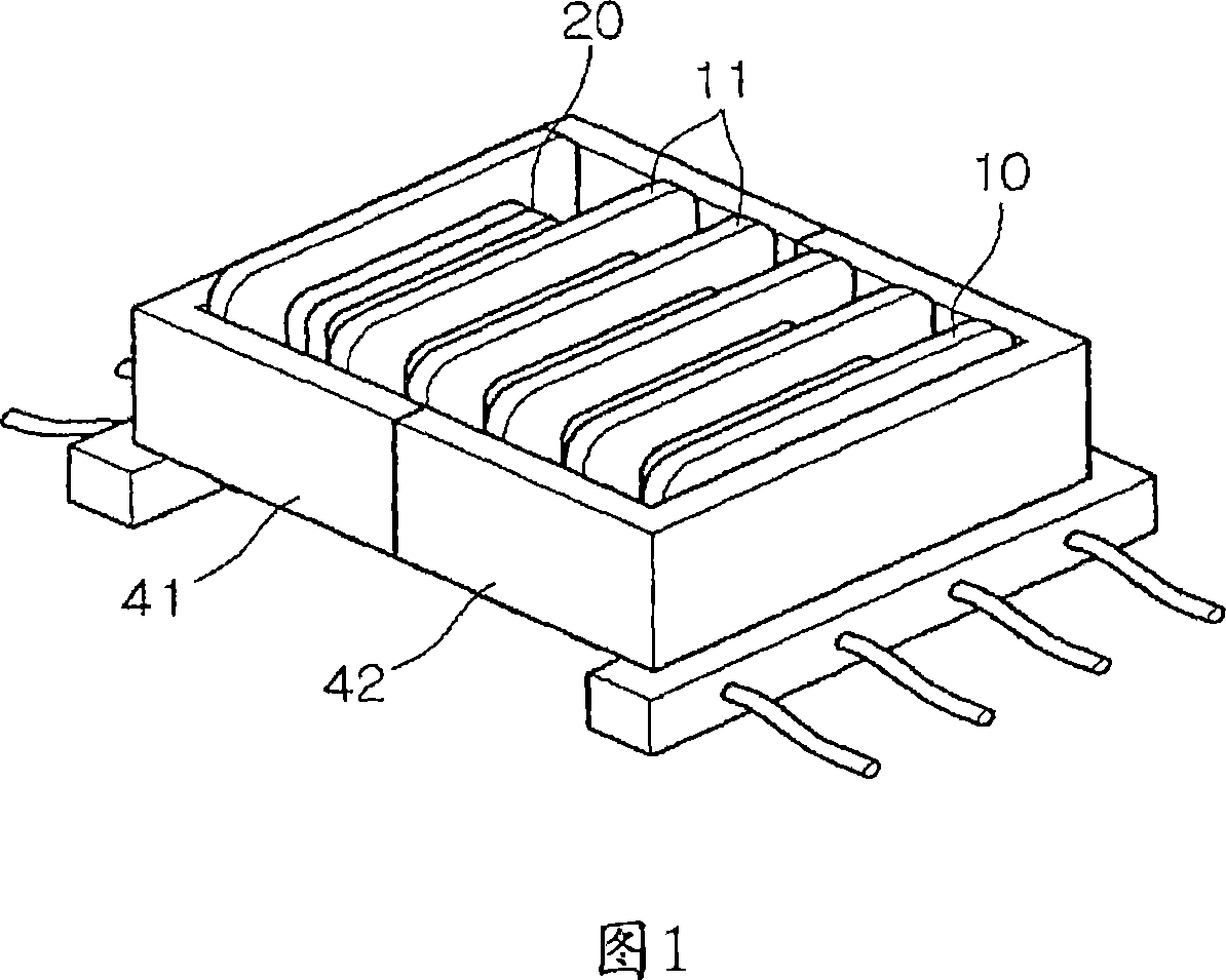
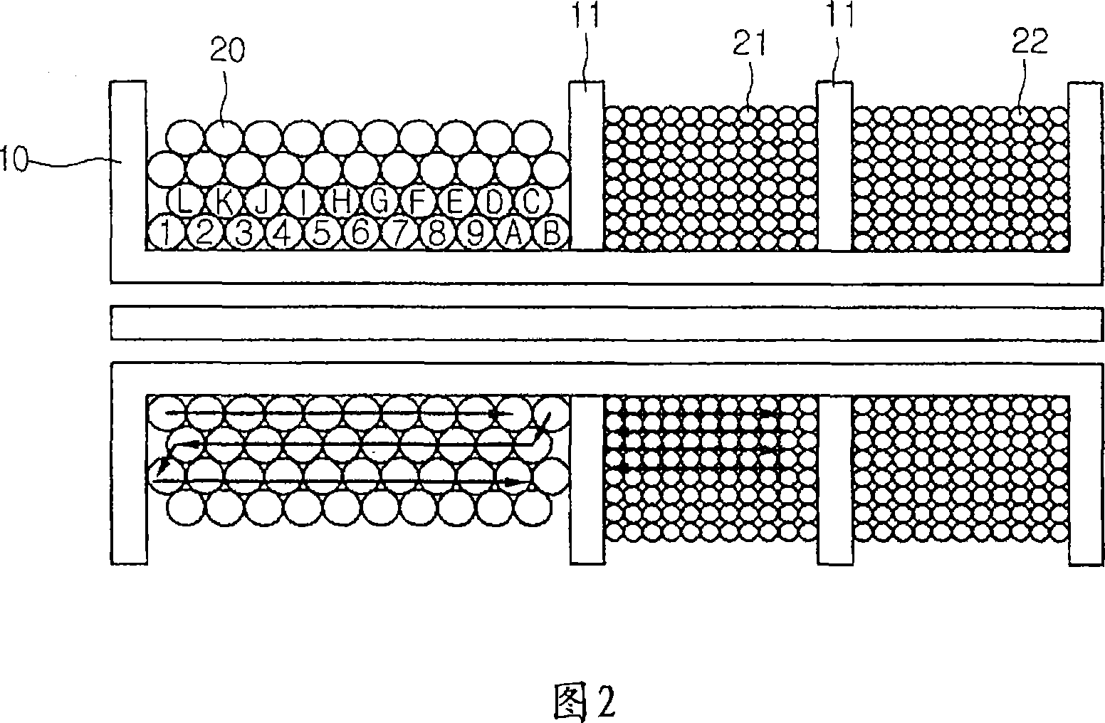
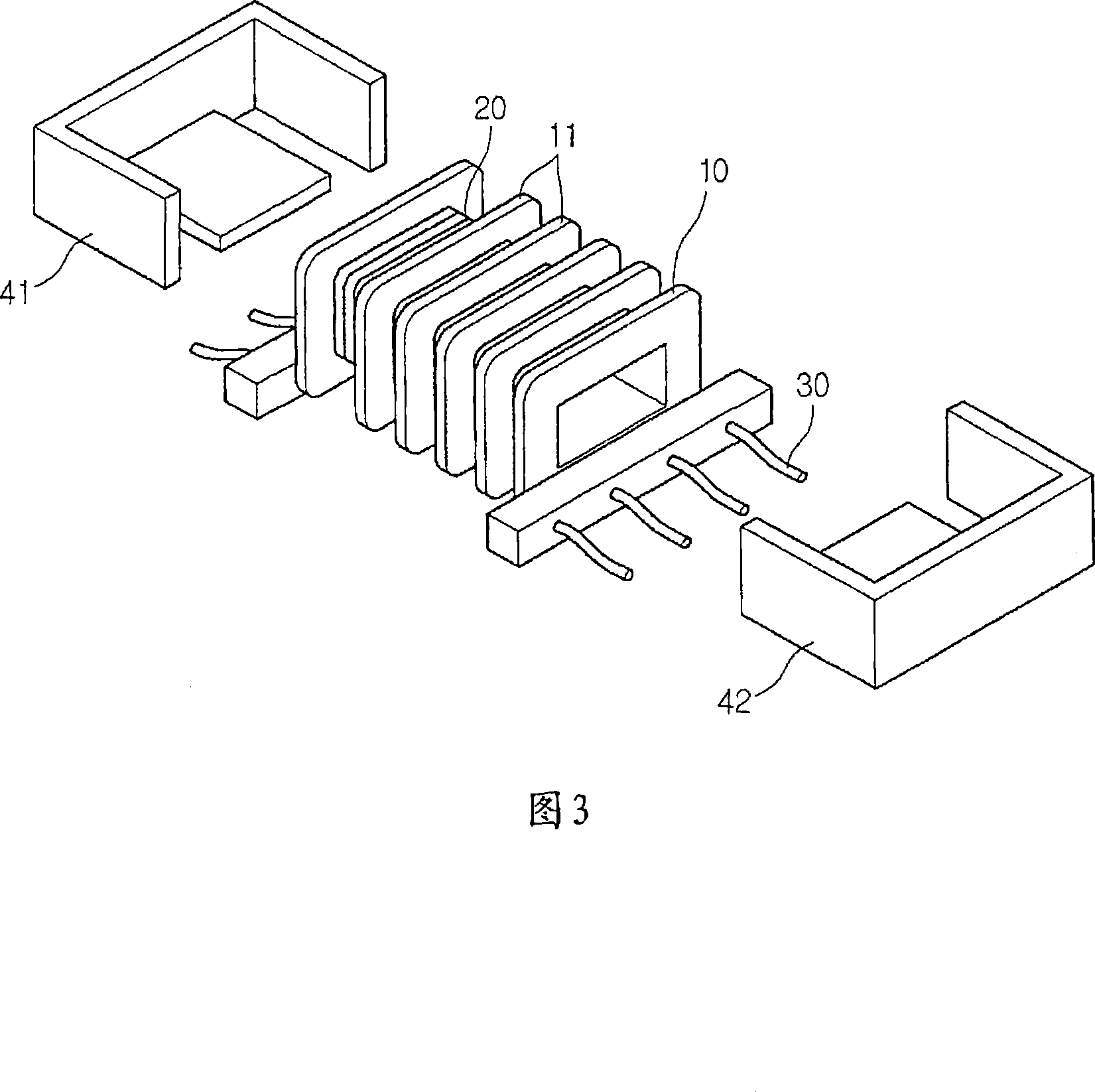
[0036] 3 is an exploded perspective view of a transformer of a lamp driving circuit according to one embodiment of the present invention, and FIG. 4 is a cross-sectional view illustrating a winding method of the transformer of the lamp driving circuit according to one embodiment of the present invention.

[0037] Referring to FIGS. 3 and 4 , a transformer for an inverter includes a bobbin 10 and ferrite cores 41 and 42 . The coil 20 is wound around the bobbin 10 and the barriers 11 are regularly formed in the bobbin 10 to be spaced apart from each other. Ferrite cores 41 and 42 are inserted into the central portion of the bobbin 10 .

[0038] The bobbin 10 having the barrier rib 11 is an injection-molded product of LCP or phenolic material, and the ferrite cores 41 and 42 are formed of fine oxides of nickel, zinc, or manganese and guide magnetic flux.

[0039] The ferrite cores 41 and 42 are formed in an E-shape, and their central portions pass through the bobbin 10 . The si...


PUM


Abstract

A transformer for an inverter includes: a bobbin including at least one barrier rib between a pair of opposing sidewalls, and a coil winding part divided into a low voltage side and a high voltage side by the barrier ribs, two or more strands of a coil being wound around the coil winding part of the low voltage side; and a ferrite core inserted into the bobbin, the ferrite core surrounding the bobbin and guiding a magnetic flux.

Description

technical field [0001] The invention relates to transformers for lamp driving circuits. Background technique [0002] Active matrix liquid crystal display devices (LCDs) use thin film transistors (hereinafter referred to as TFTs) as switching elements to display data. [0003] LCDs can be downsized compared to cathode ray tubes (CRTs) and thus are widely used in various fields including personal computers, notebook computers, office automation equipment such as copiers, and portable equipment. [0004] Since the LCD is not a self-luminous display device, it requires a light source such as a backlight. The backlight is driven by an inverter and consumes most of the power. [0005] The inverter for driving the backlight is divided into a DC / DC conversion part and a DC / AC conversion part. [0006] The DC / DC converting section can generate a DC voltage by using a pulse width modulation (PWM) mechanism and can control brightness by modulating the pulse width. [0007] The DC / ...

Claims


Application Information

Patent Timeline
Patent Type & Authority Applications(China)
IPC IPC(8): H01F27/26
CPCH01F27/325H01F2005/043H01F27/326H01F27/28H01F27/24
Inventor 朴相沃
Owner LG INNOTEK CO LTD
Why Eureka
Try Eureka