Centrifugal compressor

A technology of centrifugal compressors and electric motors, applied in the field of compressors, can solve problems such as complex structures and manufacturing processes, and achieve the effect of minimizing flow resistance

Pending Publication Date: 2021-02-02
LG ELECTRONICS INC
View PDF8 Cites 0 Cited by
  • Summary
  • Abstract
  • Description
  • Claims
  • Application Information

AI Technical Summary

Problems solved by technology

However, in the centrifugal compressor having the flow guide member as described above, since the flow guide member is respectively formed at the front end of each vane, its structure and manufacturing process are complicated.

Method used


Image

  • Centrifugal compressor
  • Centrifugal compressor
  • Centrifugal compressor

Examples


Embodiment Construction

[0031] Hereinafter, specific embodiments of the present disclosure will be described in detail with reference to the accompanying drawings.

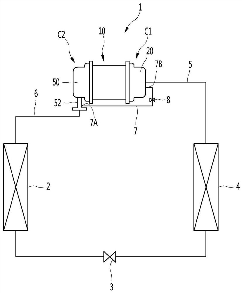
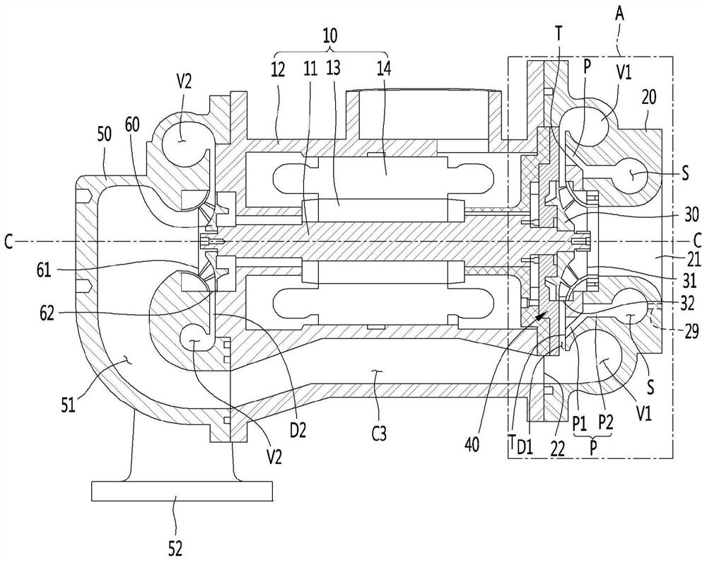
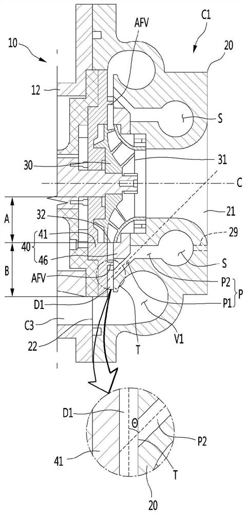
[0032] figure 1 is a diagram showing a refrigeration cycle device to which a centrifugal compressor according to an embodiment of the present disclosure is applied, figure 2 is a sectional view showing a centrifugal compressor according to an embodiment of the present disclosure, and image 3 yes figure 2 An enlarged cross-sectional view of part A is shown.

[0033] Such as figure 1 As shown, the centrifugal compressor 1 according to this embodiment can constitute a refrigeration cycle device together with the condenser 2 , the expansion mechanism 3 and the evaporator 4 . The refrigerant compressed by the centrifugal compressor 1 and then discharged from the centrifugal compressor 1 may be sucked into the centrifugal compressor 1 after sequentially passing through the condenser 2 , the expansion mechanism 3 , and the evaporator 4 ....


PUM


Abstract

A centrifugal compressor comprises: a motor having a rotational shaft; a first volute casing having a first inlet, a first volute, and a gas chamber separated from the first volute and the first inlet; a first impeller connected to one side of the rotational shaft and rotatably accommodated inside the first volute casing; a diffuser forming a diffuser path after an outlet of the first impeller andhaving a plurality of airfoil vanes provided to be spaced apart in the diffuser path; a second volute casing having an outlet, a second volute, and a second inlet through which a fluid flowing from the first volute is introduced; and a second impeller connected to the other side of the rotational shaft and rotatably accommodated inside the second volute casing, wherein at least one of the first volute casing and the diffuser has a gas adjustment path for allowing the gas chamber and the diffuser path to be in communication with each other, and a gas outlet of the gas adjustment path faces atleast one of an annular first area in which the plurality of airfoil vanes are located, and a second area between the first area and the rear end of the diffuser path.

Description

technical field [0001] The present disclosure relates to a compressor for compressing a fluid, and more particularly, to a centrifugal compressor for compressing a gas using centrifugal force. Background technique [0002] A centrifugal compressor is a device that uses its centrifugal force to compress gas by rotating a blade wheel in a housing. [0003] A centrifugal compressor may be configured to compress a gas, such as a refrigerant gas. In such a centrifugal compressor, when the driving force of the motor is transmitted to the impeller and the impeller rotates, gas is introduced into the impeller by the rotational force of the impeller. As the gas flows due to the impeller, kinetic energy increases, and the gas with increased kinetic energy passes through the diffuser and converts the kinetic energy into static pressure, thereby increasing the pressure. The gas whose pressure has been increased in this way passes through a volute and a discharge port which communicate...

Claims


Application Information

Patent Timeline
IPC IPC(8): F04D29/44F04D29/66
CPCF04D29/44F04D29/66F04D29/444F04D29/667
Inventor 金珍成金奎英韩贤旭
Owner LG ELECTRONICS INC
Why Eureka
Try Eureka