Vehicle headlamp

一种前照灯、车辆的技术,应用在车辆照明系统、车头灯、车辆部件等方向,能够解决带状部分20f宽度变窄、变形、不能解决不协调感等问题,达到提高识别性能的效果

Inactive Publication Date: 2007-07-04
KOITO MFG CO LTD
View PDF1 Cites 22 Cited by
  • Summary
  • Abstract
  • Description
  • Claims
  • Application Information

AI Technical Summary

Problems solved by technology

[0029] However, if the width of the strip-shaped portion 20f is narrowed, the strength of the upper edge 20a will decrease, which will cause problems such as deformation of the upper edge 20a when the opening 20b is processed. Therefore, it is actually impossible to make the strip-shaped portion 20f The narrowing of the width cannot solve the incongruity caused by the non-light distribution area Q, nor can it solve the problem of not being able to meet some regulations

Method used


Image

  • Vehicle headlamp
  • Vehicle headlamp
  • Vehicle headlamp

Examples


Embodiment Construction

[0070] Hereinafter, preferred embodiments of the vehicle headlamp according to the present invention will be described in detail with reference to the drawings.

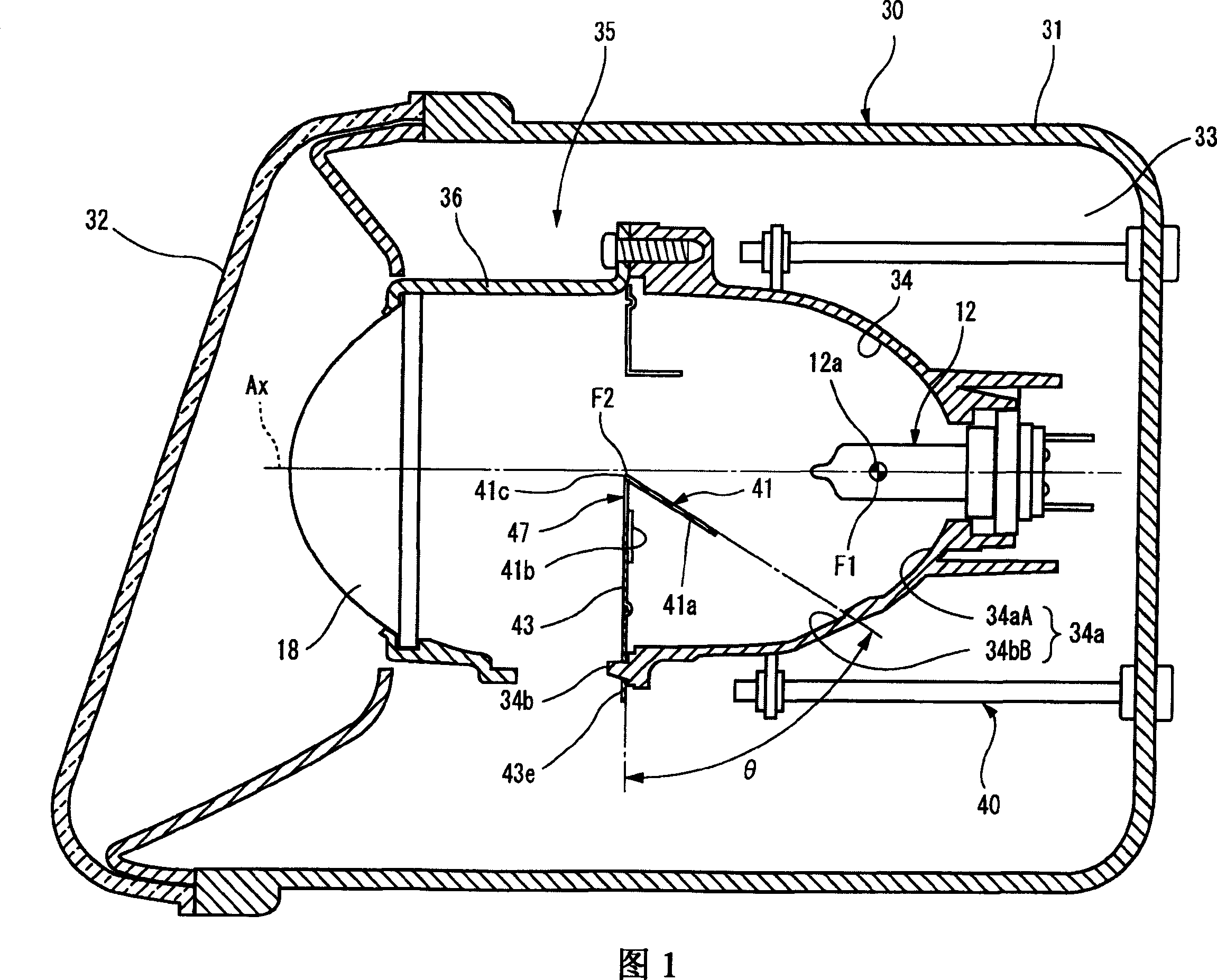
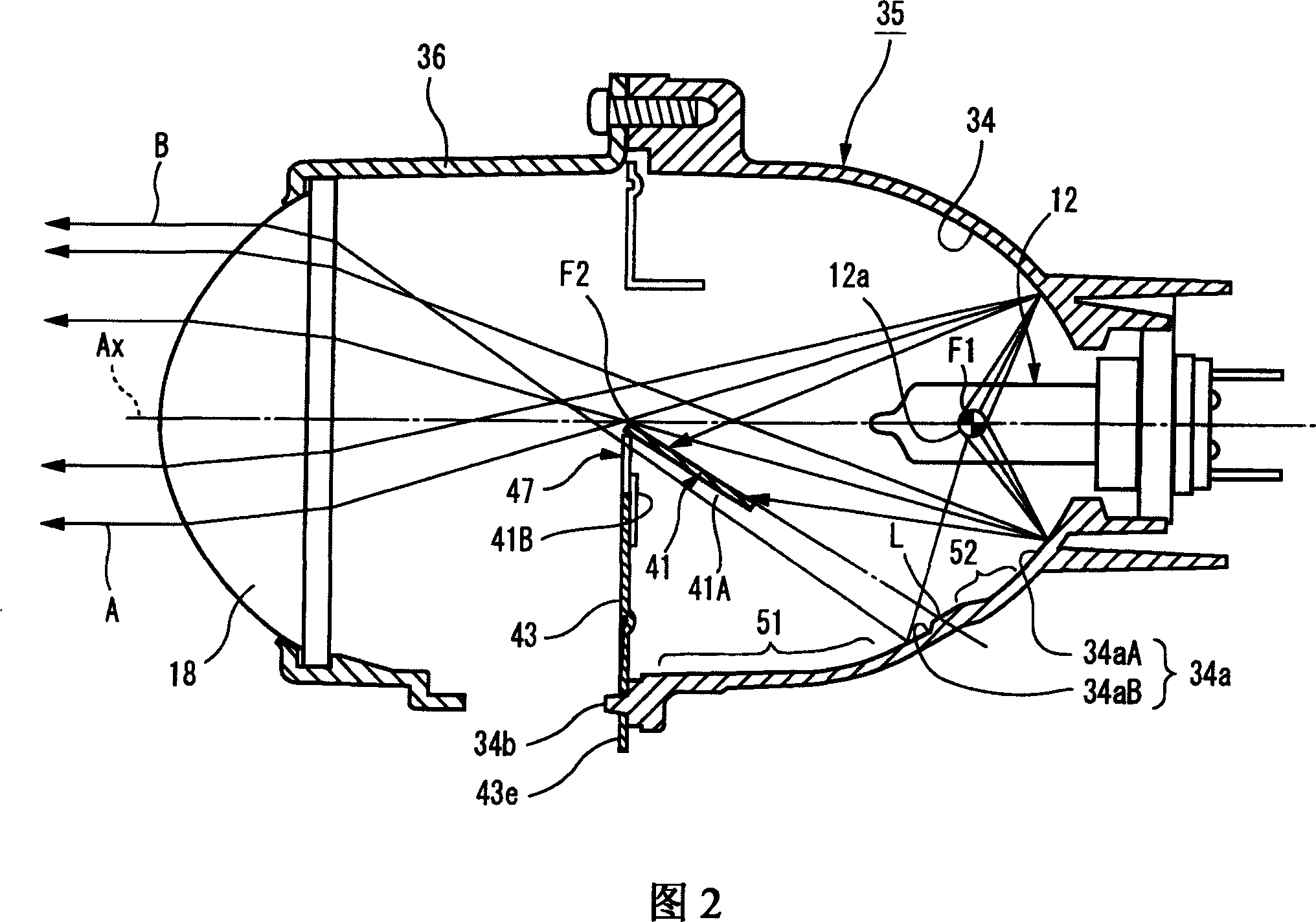
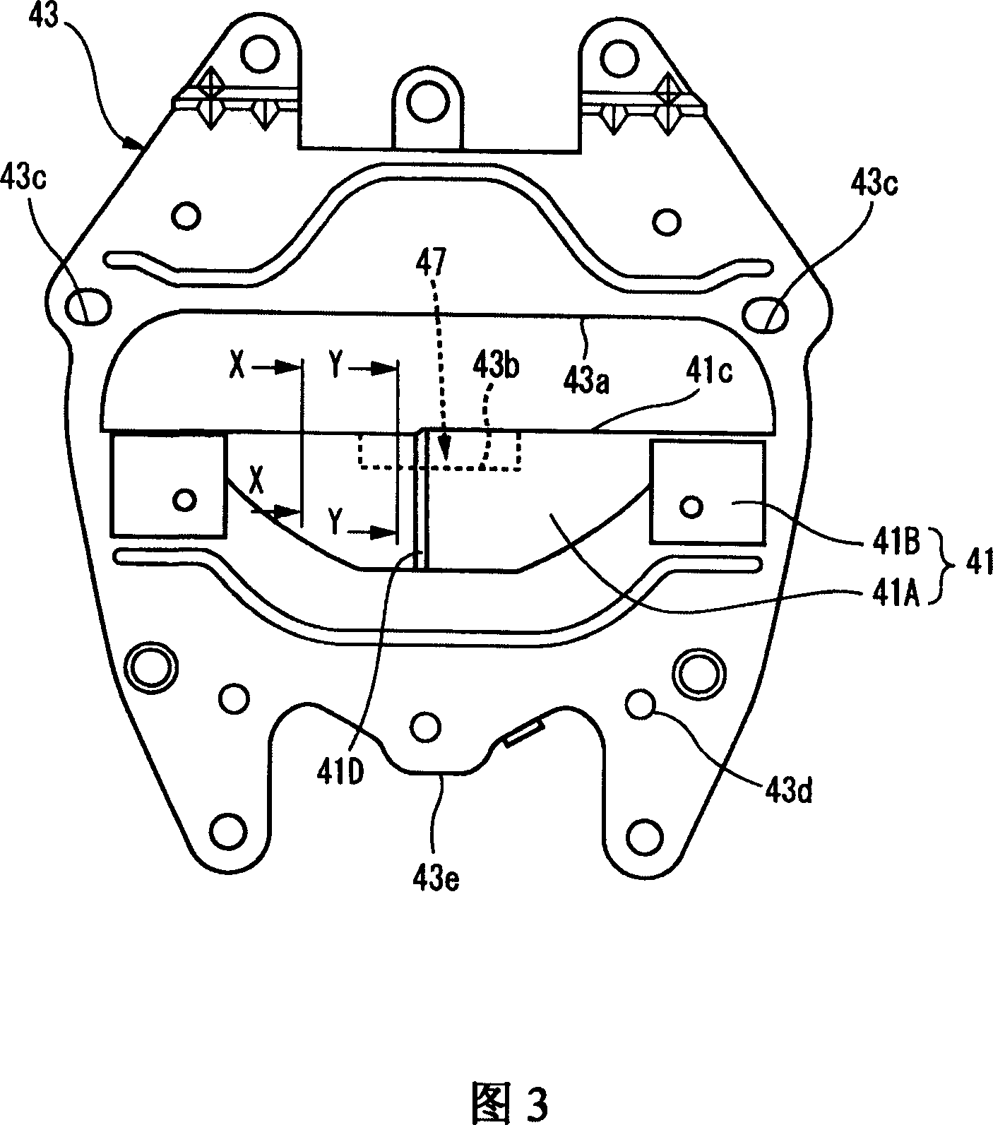
[0071] 1 is a longitudinal sectional view of a vehicle headlamp according to an embodiment of the present invention, FIG. 2 is a longitudinal sectional view of a lamp unit shown in FIG. 1 , and FIG. 3 is a rear view of a visor shown in FIG. 1 , Fig. 4 is an exploded oblique view of the shading plate and the light-dark boundary forming plate shown in Fig. 3, Fig. 5(a) and Fig. 5(b) are the X-X sectional view and the Y-Y sectional view of Fig. 3, and Fig. 6 is the sectional view shown in Fig. 1 FIG. 7 is an explanatory diagram of a light distribution pattern formed by the vehicle headlamp shown in FIG. 1 .

[0072] The vehicle headlamp 30 of the present embodiment accommodates a projection-type lamp unit 35 in a lamp chamber 33 formed of a lamp body 31 and a transparent transparent cover (lamp cover) 32 attached to the...


PUM


Abstract

The present invention provided a vehicle headlamp, which can improve the distinguishability to the high frame sign with low cost, and can irradiate reasonably to the area bewteen a light distribution pattern for irradiating the high frame sign and a cut-off line. The vehicle headlamp includes a projection lens 18, a light source 12a which is placed behind a rear focal point F2 of the projection lens 18, and a light-dark boundary forming plate 41. The light-dark boundary forming plate extends rearward and obliquely downward from a vicinity of the rear focal point F2 of the projection lens, and a light-dark boundary forming portion 41c is formed on a front end portion of the light-dark boundary forming plate 41. The light-dark boundary forming portion shields a part of the direct light from the light source 12a reflected from the reflector 34 and forms a cut-off line CL of a light distribution pattern.

Description

technical field [0001] The present invention relates to a so-called projector-type vehicle headlamp, and more particularly to a vehicle headlamp configured to illuminate an elevated sign (overhead sign). Background technique [0002] Generally, a projector-type vehicle headlamp is configured by using a reflector to reflect light from a light source arranged on an optical axis extending in the front-rear direction of the vehicle forward to close to the optical axis, and the reflected light The light is irradiated toward the front of the lamp through a projection lens provided in front of the reflector. [0003] And, when the projection type vehicle headlamp is used for short-focus light irradiation, a part of the reflected light from the reflector is provided between the projection lens and the reflector to remove the upward irradiated light. The visor irradiates light beams forward with a short-focus light distribution pattern having a predetermined cut-off line. [0004] ...

Claims


Application Information

Patent Timeline
Patent Type & Authority Applications(China)
IPC IPC(8): F21S8/10F21V13/04F21W101/10F21Y101/00
CPCF21S48/1773F21S48/145F21S48/1388F21S41/162F21S41/255F21S41/338F21S41/43F21W2102/18
Inventor 仁野直日岩城孝之盛谷知之松本昭则
Owner KOITO MFG CO LTD
Why Eureka
Try Eureka