Vertical air degermation apparatus

An air sterilization, vertical technology, used in air humidification systems, deodorization, heating methods, etc., can solve problems such as difficulty in exerting effectiveness, and achieve the effect of reducing air volume or speed

Inactive Publication Date: 2007-07-04
SANYO ELECTRIC CO LTD
View PDF1 Cites 10 Cited by
  • Summary
  • Abstract
  • Description
  • Claims
  • Application Information

AI Technical Summary

Problems solved by technology

[0003] However, although the above-mentioned sterilizing device can be effective in a small space where the electrolyte mist in the form of particles is easy to reach, it can be used in environments where the elec

Method used


Image

  • Vertical air degermation apparatus
  • Vertical air degermation apparatus
  • Vertical air degermation apparatus

Examples


Embodiment Construction

[0057] Hereinafter, embodiments of the present invention will be described with reference to the drawings.

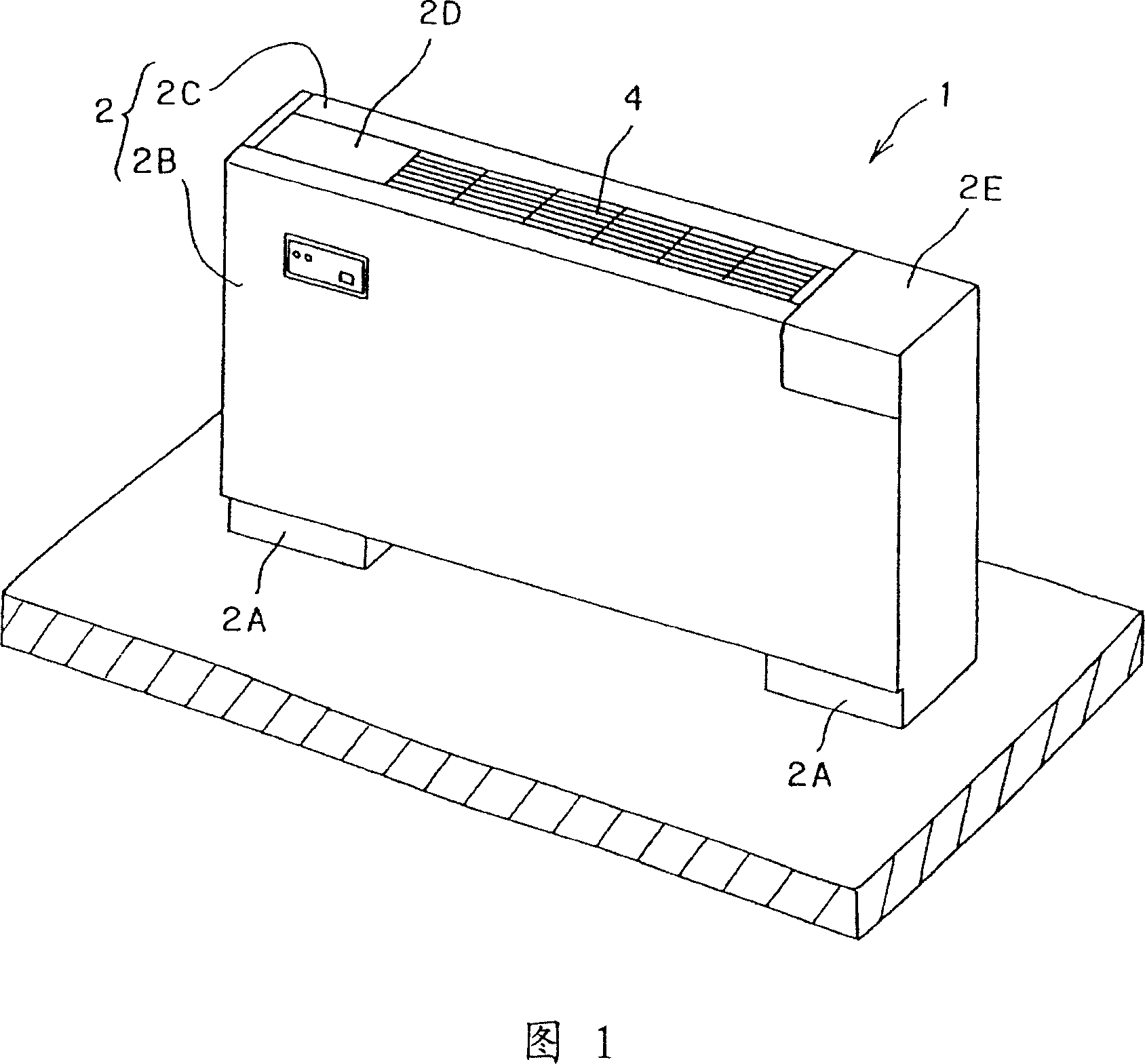
[0058] In Fig. 1, reference numeral 1 denotes a vertical air sterilization device. The vertical air sterilization device 1 has a box-shaped frame body 2, which includes a stand 2A, a front plate 2B, and a top plate 2C, and an operation cover 2D and an opening and closing cover 2E are arranged in rows on both sides of the top plate 2C. .

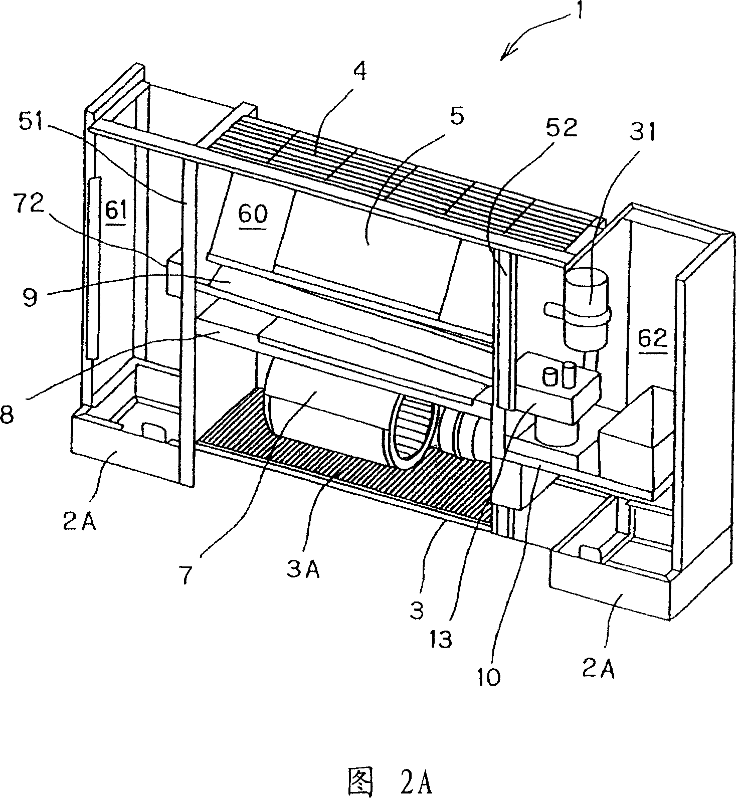
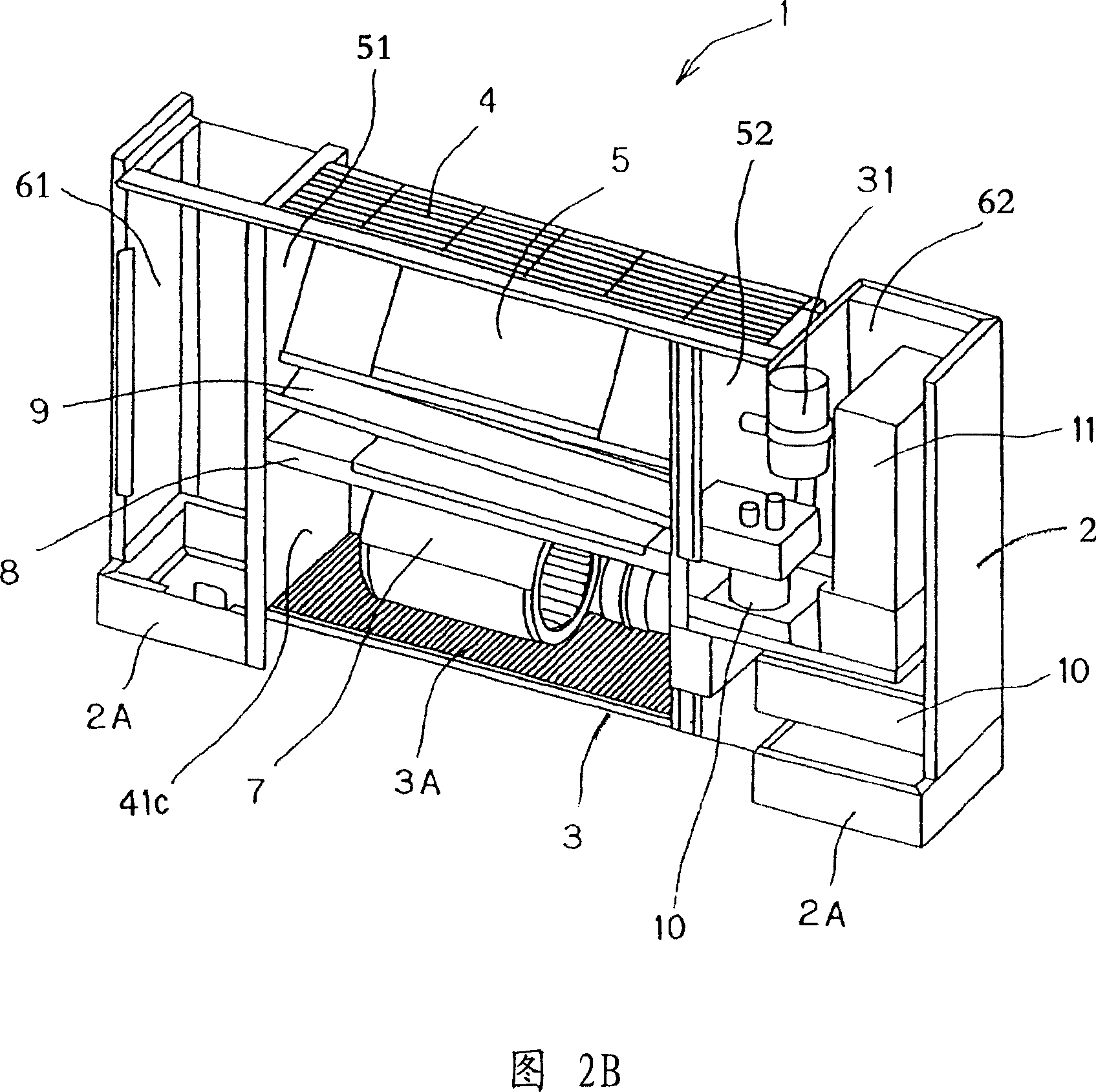
[0059] As shown in Figure 2, the inside of frame body 2 is provided with two partitions 51,52 extending in the up and down direction, by these partitions 51,52 the inside of above-mentioned frame body 2 is divided into three chambers (sterilizing chamber 60 , Electrical equipment room 61, water supply room 62). A horizontally long air inlet 3 is formed at the lower portion of a sterilization chamber (one chamber) 60 formed in the center of the housing 2 , and a prefilter 3A is disposed above the air inlet 3 . A blower fan 7 is arran...


PUM


Abstract

An air filtering apparatus according to the present invention including a housing (2), at least one partition plate (51, 52) for partitioning the inside of the housing into at least two chambers (60, 61, 62), a gas-liquid contact member (5) for receiving electrolytic water from an electrolytic water supply unit, an air blowing fan (7) for blowing air to the gas-liquid contact member so that the air is brought into contact with the electrolytic water flowing along the gas-liquid contact member, a controller (52, 53) for controlling the floor-mount type air filtering apparatus, and a water receiving tray (9) for receiving the electrolytic water flowing out from the gas-liquid contact member, wherein the gas-liquid contact member (5) and the air blowing fan (7) being disposed in one of the chambers (60), and one of the controller and the electrolytic water supply unit being disposed in the other chamber (61, 62) of the at least two chambers.

Description

technical field [0001] The present invention relates to, for example, a portable vertical air sterilization device capable of removing airborne microorganisms and viruses. Background technique [0002] In general, for the purpose of removing airborne microorganisms and viruses, there has been proposed a sterilizing device that diffuses electrolyte mist into the air and makes the electrolyte mist directly contact airborne microorganisms to inactivate viruses and the like. In this sterilization device, in order to diffuse the electrolyte mist into the air, the water containing hypochlorous acid is applied to the humidifying element (gas-liquid contact part) made of non-woven fabric and soaked, and the wind of the blower and the humidifying element contact, thereby releasing the moisture from the humidifying element. (For example, refer to JP-A-2002-181358). [0003] However, although the above-mentioned sterilizing device can be effective in a use environment where the elect...

Claims


Application Information

Patent Timeline
IPC IPC(8): F24F6/00A61L9/00
Inventor 福岛纪雄内田阳一薄井宏明荒川彻小山浩司田村隆明高桥一夫水间圣人
Owner SANYO ELECTRIC CO LTD
Why Eureka
Try Eureka