Magnetron

A magnetron and cathode technology, applied in the field of magnetrons, can solve the problems of reducing the efficiency of magnetrons

Inactive Publication Date: 2007-07-04
LG ELECTRONICS INC
View PDF0 Cites 4 Cited by
  • Summary
  • Abstract
  • Description
  • Claims
  • Application Information

AI Technical Summary

Problems solved by technology

Therefore, the efficiency of the magnetron decreases

Method used


Image

  • Magnetron
  • Magnetron
  • Magnetron

Examples


Embodiment Construction

[0028] Reference will now be made in detail to the preferred embodiments of the invention, examples of which are illustrated in the accompanying drawings.

[0029] Hereinafter, the first embodiment according to the present invention will be described in more detail.

[0030] Components identical to those previously described will be given the same reference numerals.

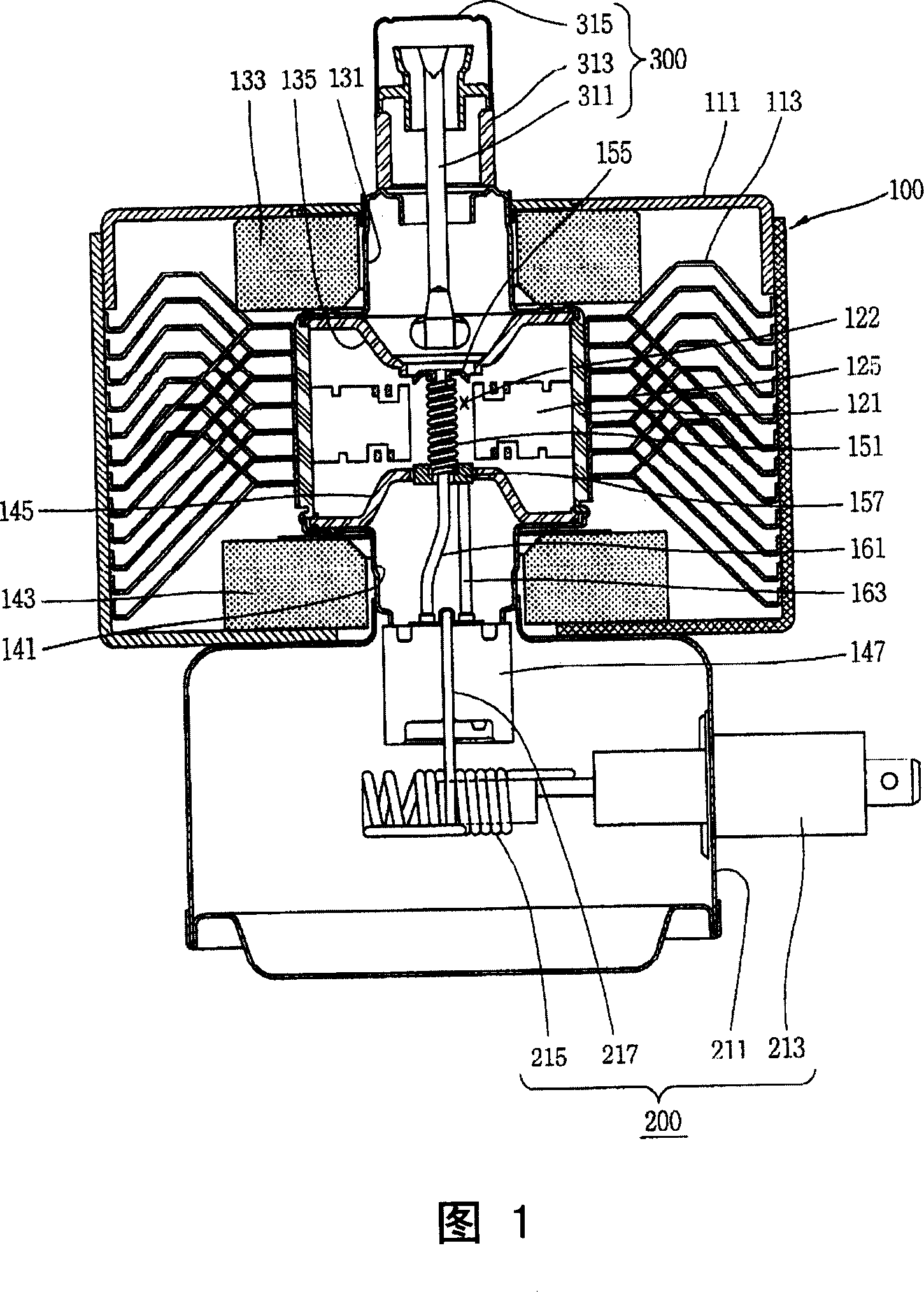
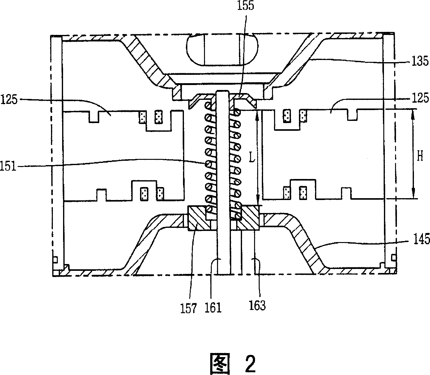
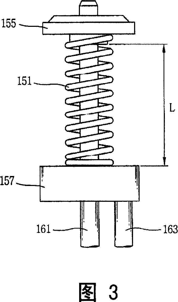
[0031] As shown in FIGS. 4 to 6, the magnetron according to the present invention includes: a high-frequency generating unit 100 placed between an input unit 200 for supplying power and an output unit 300 for outputting high-frequency energy, for providing high frequency. The high-frequency generating unit 100 includes: the anode 121, which is cylindrical; a plurality of blades 125, which are arranged in the anode 121; the upper magnetic pole 135 and the lower magnetic pole 145, which are respectively arranged above and below the anode 121; the cathode 171, which is spiral, Provided at the center of the anode ...


PUM


Abstract

A magnetron comprises an anode, a cathode disposed at a center of the anode, a plurality of vanes radially protruding from an inner surface of the anode towards the cathode, and an upper end shield and a lower end shield respectively coupled to an upper end and a lower end of the cathode so that a length of an effective heating portion of the cathode may be less than a height of the vane. A heating power for the cathode is reduced thus to decrease an input power for the same output, thereby enhancing an efficiency of the magnetron.

Description

technical field [0001] The present invention relates to a magnetron, more particularly, to a magnetron capable of improving efficiency by reducing the input power to obtain the same output power by reducing the thermal power of the cathode. Background technique [0002] Generally, magnetrons are used in the microwave field, plasma lighting equipment, dryers, and other high-frequency systems. The magnetron includes: a high-frequency generating unit that generates high-frequency energy through an electromagnetic field; an input unit that supplies power to the high-frequency generating unit; and an output unit that emits high-frequency energy generated from the high-frequency generating unit. [0003] 1 is a sectional view showing a magnetron according to the related art, FIG. 2 is an enlarged view showing a main part of FIG. 1 , and FIG. 3 is a side view showing a cathode of FIG. 2 . [0004] As shown in the figure, the magnetron includes: a high-frequency generating unit 100...

Claims


Application Information

Patent Timeline
Patent Type & Authority Applications(China)
IPC IPC(8): H01J25/50H01J23/02
CPCH01J23/05H05B6/74H01J25/587H01J23/16
Inventor 李钟寿
Owner LG ELECTRONICS INC
Why Eureka
Try Eureka