
Sealing cushion

A sealing gasket and sealing lip technology, applied in the direction of engine sealing, engine components, mechanical equipment, etc., can solve the problems of difficult elastic deformation, poor installation, difficult to press into the opening of the casing, etc., to eliminate the bad situation. Effect

Inactive Publication Date: 2007-07-04
NOK CORP
View PDF4 Cites 14 Cited by
  • Summary
  • Abstract
  • Description
  • Claims
  • Application Information

AI Technical Summary

Problems solved by technology

According to this prior art, since it is generally believed that the annular lip is an extruded lip with a mountain-shaped cross-section, and compressive deformation occurs in the radial direction when pressed in, it is difficult to produce elastic deformation in the radial direction, so it is difficult to press into the housing openings, resulting in poor installability

Method used


Image

  • Sealing cushion
  • Sealing cushion
  • Sealing cushion

Examples


no. 1 example

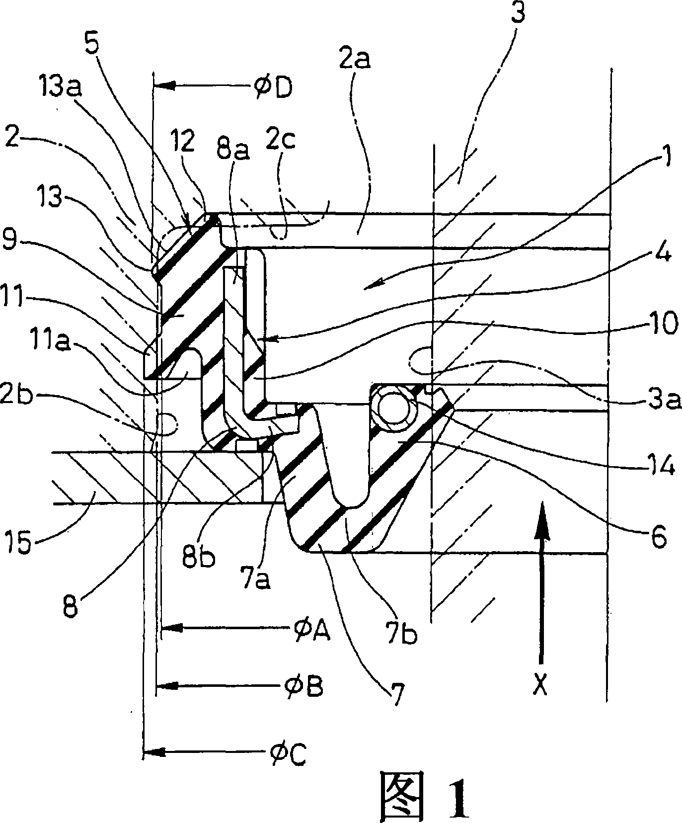
[0068] Fig. 1 is a half-sectional view of the gasket 1 according to the first embodiment of the present invention;

[0069] The gasket 1 described in this embodiment is used to seal between the resin cylinder head 2 and the spark plug barrel 3 in an internal combustion engine, and is installed on the inner peripheral surface 2b of the opening 2a of the cylinder head 2, and it is closely attached to the above-mentioned plug. The outer peripheral surface 3a of the spark plug barrel 3 at the opening 2a is structured as follows. In addition, the gasket 1 is configured to be pushed into the opening 2 a of the cylinder head 2 from the inner side of the cylinder head 2 (lower side in the figure) (arrow X direction).

[0070] First, this gasket (spark plug gasket) 1 is integrally formed with: an outer peripheral mounting portion 5 which is annular and fits on the inner peripheral side of the cylindrical inner peripheral surface 2b of the opening 2a in the cylinder head 2; 6, which is...

no. 4 example

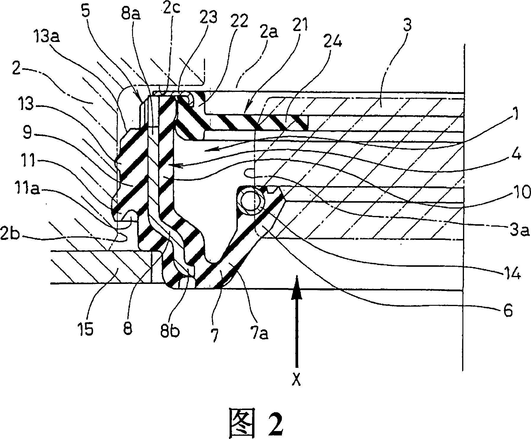
[0083]In the above-mentioned first to third embodiments (FIGS. 1 to 3), the gasket 1 is configured to be pressed into the opening 2a of the cylinder head 2 from the inside (downward in the figure) of the cylinder head 2, but the structure is also The opening 2 a of the cylinder head 2 may be pushed in from the outside (upper in the figure) instead of the inside of the cylinder head 2 . At this time, as shown in FIG. 4 , the lip-shaped interference amount setting member 11 is arranged to face the reverse of the push-in direction (direction of arrow X), that is, upward in the figure. In addition, a radial position determining element 13 is provided below the drawing of the lip-shaped interference amount setting element 11. The radial position determining element 13 is not in the shape of a protrusion, but corresponds to the inner peripheral surface 2b of the opening of the cylinder head 2. The tapered object that is provided and is in close contact with the tapered radial positi...

no. 5 example

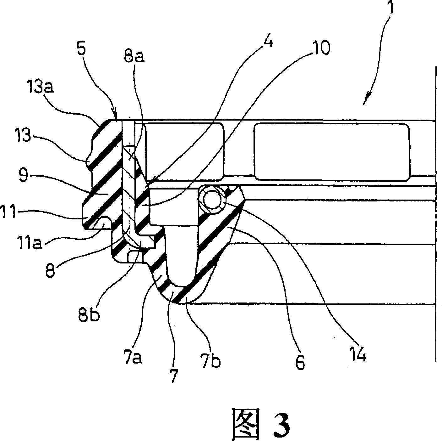
[0085] Moreover, as shown in FIG. 5, the flange part 8b may be provided in the rear end part of the metal ring 8 in the pushing direction of the cylindrical part 8a.


PUM


Abstract

A gasket installed on the inner peripheral surface of an opening of a housing such as a cylinder head cover and sealing the gap between the housing and an insertion member such as a plug tube inserted in the opening. The gasket has good installability, so that, even if the inner diameter of the opening is not made to high precision, an outer periphery installation section of the gasket is prevented from being nipped in fitting of the gasket into the housing, or the gasket can be reliably fitted into the housing. To achieve the above, the outer diameter of the outer periphery installation section is set equal to or less than the inner diameter of the opening, and a tightening allowance setting means and a radial direction positioning means are provided on an outer peripheral section of the outer periphery installation section of the gasket. The tightening allowance setting means sets a tightening allowance of the gasket relative to the inner peripheral surface of the opening, and the radial direction positioning means performs radial positioning of the gasket relative to the inner peripheral surface of the opening. The tightening allowance setting means is inclined in the axially opposite direction to the direction of fitting of the gasket into the housing and has a lip shape whose outer diameter in a free state is set greater than the inner diameter of the opening.

Description

technical field [0001] The invention relates to a gasket in a sealing device. The gasket of the present invention is used in the field of automobiles or general production machinery, for example, it is used to seal between the cylinder head and the spark plug barrel of the internal combustion engine in the automobile related field, or between the cylinder head and the injection pipe. Background technique [0002] In order to seal, for example, between the cylinder head and the spark plug barrel in an internal combustion engine, a spark plug barrel gasket 51 as shown in FIG. , which are integrally formed with: an outer peripheral mounting portion 53, which is pressed into the inner peripheral surface 52b of the opening portion 52a of the cylinder head 52 as a housing; the outer peripheral surface 54 a of the spark plug barrel 54 ; and, the eccentric driven portion 56 provided between the outer peripheral mounting portion 53 and the seal lip portion 55 . [0003] However, in...

Claims


Application Information

Patent Timeline
Patent Type & Authority Applications(China)
IPC IPC(8): F16J15/12
CPCF16J15/3276F16J15/3212F16J15/3268F16J15/3224
Inventor 柳得德
Owner NOK CORP
Learn More