
Activation of carbon nanotubes for field emission applications

A carbon nanotube and field emission technology, which is applied in the manufacture of electrical components, circuits, semiconductors/solid-state devices, etc., can solve problems that hinder the application of CNT emission, and achieve the effects of low cost, good uniformity, and convenient processing

Inactive Publication Date: 2007-07-11
NANO
View PDF1 Cites 43 Cited by
  • Summary
  • Abstract
  • Description
  • Claims
  • Application Information

AI Technical Summary

Problems solved by technology

Clearly, all of these issues hamper various field emission applications of CNTs

Method used

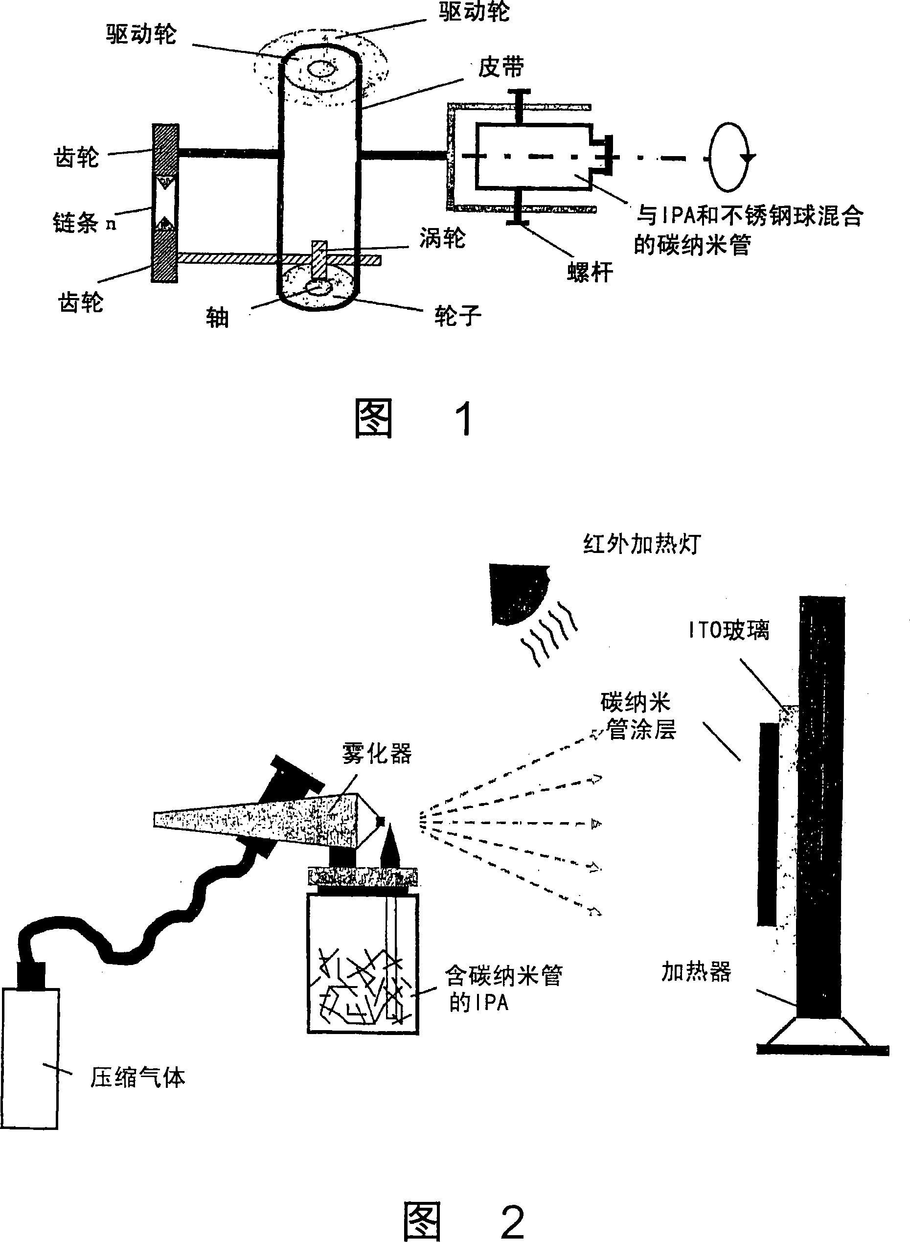
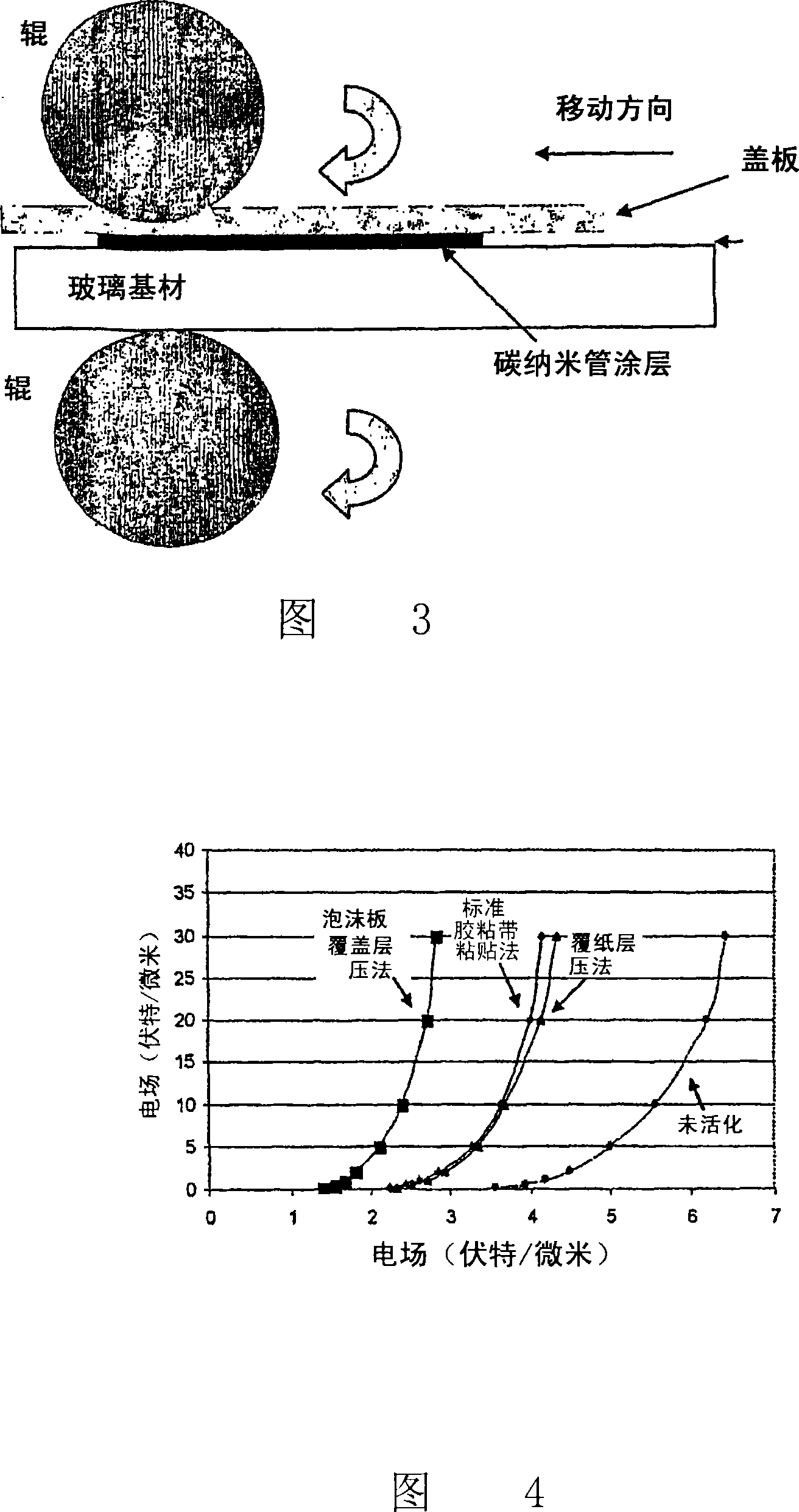

Image

  • Activation of carbon nanotubes for field emission applications
  • Activation of carbon nanotubes for field emission applications
  • Activation of carbon nanotubes for field emission applications

Examples


Embodiment Construction

[0028] The following description provides numerous specific details to facilitate a thorough understanding of the present invention. It will be apparent, however, to one skilled in the art that the present invention may be practiced without these specific details. In other instances, well-known circuits are shown in block diagram form in order not to obscure the invention with unnecessary detail. In many instances, details regarding timing, etc., have been left out as such details are not necessary for a complete understanding of the invention and are within the skill of those skilled in the relevant art.

[0029] Referring now to the drawings, elements shown in the figures are not necessarily to scale, and like or similar elements are designated by the same reference numerals throughout the several views.

[0030] 1. Sources of carbon nanotubes and alumina powder

[0031] Unpurified single-walled carbon nanotubes (SWNTs) (available from CarboLex, Inc., Lexington, Kentucky, ...


PUM

PropertyMeasurementUnit
diameteraaaaaaaaaa
thicknessaaaaaaaaaa
thicknessaaaaaaaaaa

Abstract

Substantially enhanced field emission properties are achieved by using a process of covering a non-adhesive material (for example, paper, foam sheet, or roller) over the surface of the CNTs, pressing the materiel using a certain force, and removing the material.

Description

technical field [0001] This invention relates generally to field emitters, and more particularly to field emitters using carbon nanotubes. Background of the invention [0002] Due to their incredible physical, chemical, electronic and mechanical properties, carbon nanotubes (CNTs) have been studied by many companies and research institutions [Walt A. de Heer, "Nanotubes and the Pursuit of Applications", MRS Bulletin 29( 4), pp.281-285(2004)]. They can be used as excellent cold electron sources in many applications such as displays, microwave sources, X-ray tubes, etc., because of their excellent field emission properties and chemical inertness, very stable operation at low voltages for long periods of time (ZviYaniv , "The status of the carbon electron emitting films for display and microelectronic applications", The International Display Manufacturing Conference, January 29-31, 2002, Seoul, Korea). It has been demonstrated that aligned carbon nanotubes have excellent fiel...

Claims


Application Information

Patent Timeline
Patent Type & Authority Applications(China)
IPC IPC(8): H01L21/00H01L21/469
Inventor 茅东升R·芬克Z·雅尼弗
Owner NANO
Learn More