X-ray detector, imaging apparatus and calibration method

a technology of x-ray detector and imaging apparatus, applied in the field of x-ray detector, xray detection apparatus, imaging apparatus and calibration method, can solve the problems of inability to use above two energy calibration methods, and inability to perform a complete energy calibration, etc., to achieve the effect of improving calibration

Active Publication Date: 2018-06-19
KONINKLJIJKE PHILIPS NV
View PDF5 Cites 5 Cited by
  • Summary
  • Abstract
  • Description
  • Claims
  • Application Information

AI Technical Summary

Benefits of technology

[0010]It is an object of the present invention to provide an x-ray detector, an x-ray detection apparatus, an imaging apparatus and a calibration method for calibrating an x-ray detector which enable an improved calibration without the above mentioned drawbacks.
[0038]According to an embodiment said evaluation unit is configured to perform a threshold scan to obtain said first and second electrical measurement signals. Such a threshold scan and how to perform it is generally known, e.g. from Christian Bäumer et al., “Testing an Energy-Dispersive Counting-Mode Detector With Hard X-Rays From a Synchrotron Source”, IEEE TRANSACTIONS ON NUCLEAR SCIENCE, VOL. 55, NO. 3, JUNE 2008. This provides a rather easy but reliable way to obtain said first and second electrical measurement signals.
[0040]Preferably, the x-ray detection apparatus comprises a single light source for coupling light into the semiconductor layer. In other embodiments the x-ray detection apparatus comprises a plurality of light sources, in particular a single light source per pixel or group of pixels, for coupling light into the semiconductor layer. The number of light sources generally depends on the current design and any mechanical constraints, particularly with respect to the arrangement of the light source(s). Using two different sources avoids the need to switch intensities. Alternatively, source 1 can be used for E1, source 2 for E2, sources 1+2 for E3=E1+E2, i.e. no source for the noise peak.

Problems solved by technology

This alternative is useful in combination with one of the above methods but cannot be used to perform a complete energy-calibration because it provides only one reference energy.
The problems with above two methods of energy calibration are numerous.
The use of gamma ray sources is problematic due to the radiation aspect and due to continuously changing activity of the source.
Besides that a very close distance needs to be maintained during the calibration measurement which is unpractical for an entire detector array like the ones used for computed tomography or even mammography.
Further, this method suffers from low x-ray fluxes and, hence, long calibration times. The use of K-edge filters is more practical because x-ray tubes can be used.
However, the extraction of the K-edge attenuation feature is less trivial and often leads to erroneous measurements of the energy reference.
Further, polychromatic sources combined with K-edge filtration suffer from the difficult process of extracting the K-edge feature from the measured spectra, in particular for realistic spectral response functions, like observed in millimeter-sized CdTe of CZT detectors, most likely candidates for future photon counting CT scanners.

Method used


Image

  • X-ray detector, imaging apparatus and calibration method
  • X-ray detector, imaging apparatus and calibration method
  • X-ray detector, imaging apparatus and calibration method

Examples


Embodiment Construction

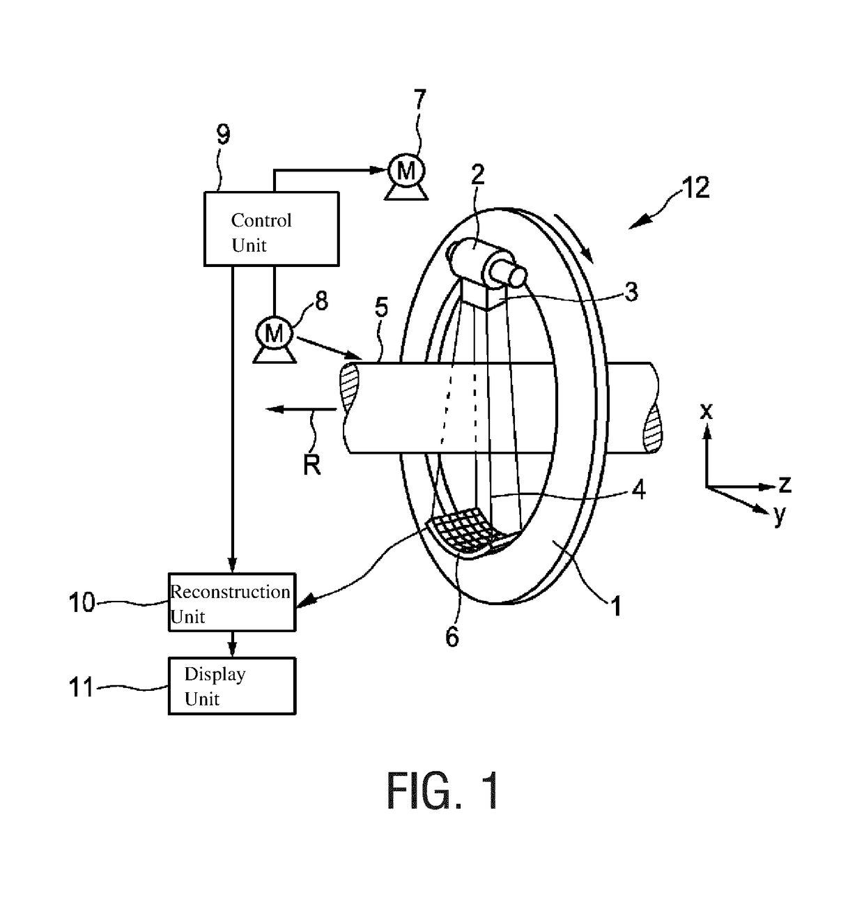
[0054]FIG. 1 shows schematically and exemplarily an imaging apparatus 12 according to the present invention for imaging an object, in this example being a computed tomography (CT) apparatus. The CT apparatus 12 includes a gantry 1, which is capable of rotation about a rotational axis R, which extends parallel to a z direction. A radiation source 2 (also called photon source), which may be a polychromatic x-ray tube, is mounted on the gantry 1. The radiation source 2 is provided with a collimator 3, which forms a (e.g. conical) radiation beam 4 from the radiation (photons) generated by the radiation source 2. The radiation traverses an object of examination, such as a patient, arranged in an (e.g. cylindrical) imaging area 5 (also called examination zone). After having traversed the imaging area 5, the radiation beam 4 is incident on an x-ray detector 6, which comprises a two-dimensional detection surface. The detector 6 is also mounted on the gantry 1.

[0055]The CT apparatus 12 compr...


PUM


Abstract

An X-ray detector comprises a directly converting semiconductor layer having a plurality of pixels for converting incident radiation into electrical measurement signals with a band gap energy characteristic of the semiconductor layer, wherein said incident radiation is x-ray radiation emitted by an x-ray source or light omitted by at least one light source. An evaluation unit calculates evaluation signals per pixel or group of pixels from first electrical measurement signals generated when light from said at least one light source at a first intensity is coupled into the semiconductor layer, and second electrical measurement signals generated when light from said at least one light source at a second intensity is coupled into the semiconductor layer. A detection unit determines detection signals from electrical measurement signals generated when x-ray radiation is incident onto the semiconductor layer, and a calibration unit calibrates the detection unit on the basis of the evaluation signals.

Description

CROSS REFERENCE TO RELATED APPLICATIONS[0001]This application is the U.S. National Phase application under 35 U.S.C. § 371 of International Application No. PCT / EP2015 / 079175, filed Dec. 9, 2015, published as WO 2016 / 091981 on Jun. 16, 2016, which claims the benefit of European Patent Application Number 14197459.2 filed Dec. 11, 2014. These applications are hereby incorporated by reference herein.FIELD OF THE INVENTION[0002]The present invention relates to an x-ray detector, an x-ray detection apparatus, an imaging apparatus and a calibration method for calibrating an x-ray detector.BACKGROUND OF THE INVENTION[0003]Energy calibration in semiconductor detectors (also called photon counting detectors, as e.g. known from WO 2014 / 087290 A1) is conventionally performed by use of gamma ray sources of known energy or by use of K-edge filters.[0004]In the method using gamma ray sources the pixel array is irradiated with a mono-chromatic gamma ray source of known energy. The irradiation needs...

Claims


Application Information

Patent Timeline
Patent Type & Authority Patents(United States)
IPC IPC(8): G01T1/24A61B6/00H05G1/08G01T7/00H01J35/02
CPCG01T1/24A61B6/585H05G1/08G01T7/005H01J35/02
Inventor ROESSL, EWALDDAERR, HEINER
Owner KONINKLJIJKE PHILIPS NV
Why Eureka
Try Eureka