Supercharge Your Innovation With Domain-Expert AI Agents!

Inspection apparatus, inspection method, lithographic apparatus and manufacturing method

a technology of inspection apparatus and manufacturing method, which is applied in the field of inspection apparatus, can solve the problems of complex selection process, inability to meet the design requirements of users of lithographic apparatus, and inability to meet the requirements of lithographic apparatus design rules,

Active Publication Date: 2018-06-19
ASML NETHERLANDS BV
View PDF25 Cites 0 Cited by
  • Summary
  • Abstract
  • Description
  • Claims
  • Application Information

AI Technical Summary

Benefits of technology

This approach provides a robust and efficient method for monitoring focus and dose parameters, reducing sensitivity to process and tool effects, and eliminating the requirement for specific DBF structures, thereby improving the accuracy and consistency of lithographic processes.

Problems solved by technology

Such structures may contravene design rules of the users of lithographic apparatuses.
This selection process can be complex and require significant effort to find a suitable target geometry.
It may even be the case that no suitable target geometry exists.

Method used


Image

  • Inspection apparatus, inspection method, lithographic apparatus and manufacturing method
  • Inspection apparatus, inspection method, lithographic apparatus and manufacturing method
  • Inspection apparatus, inspection method, lithographic apparatus and manufacturing method

Examples


Embodiment Construction

[0026]Before describing embodiments of the invention in detail, it is instructive to present an example environment in which embodiments of the present invention may be implemented.

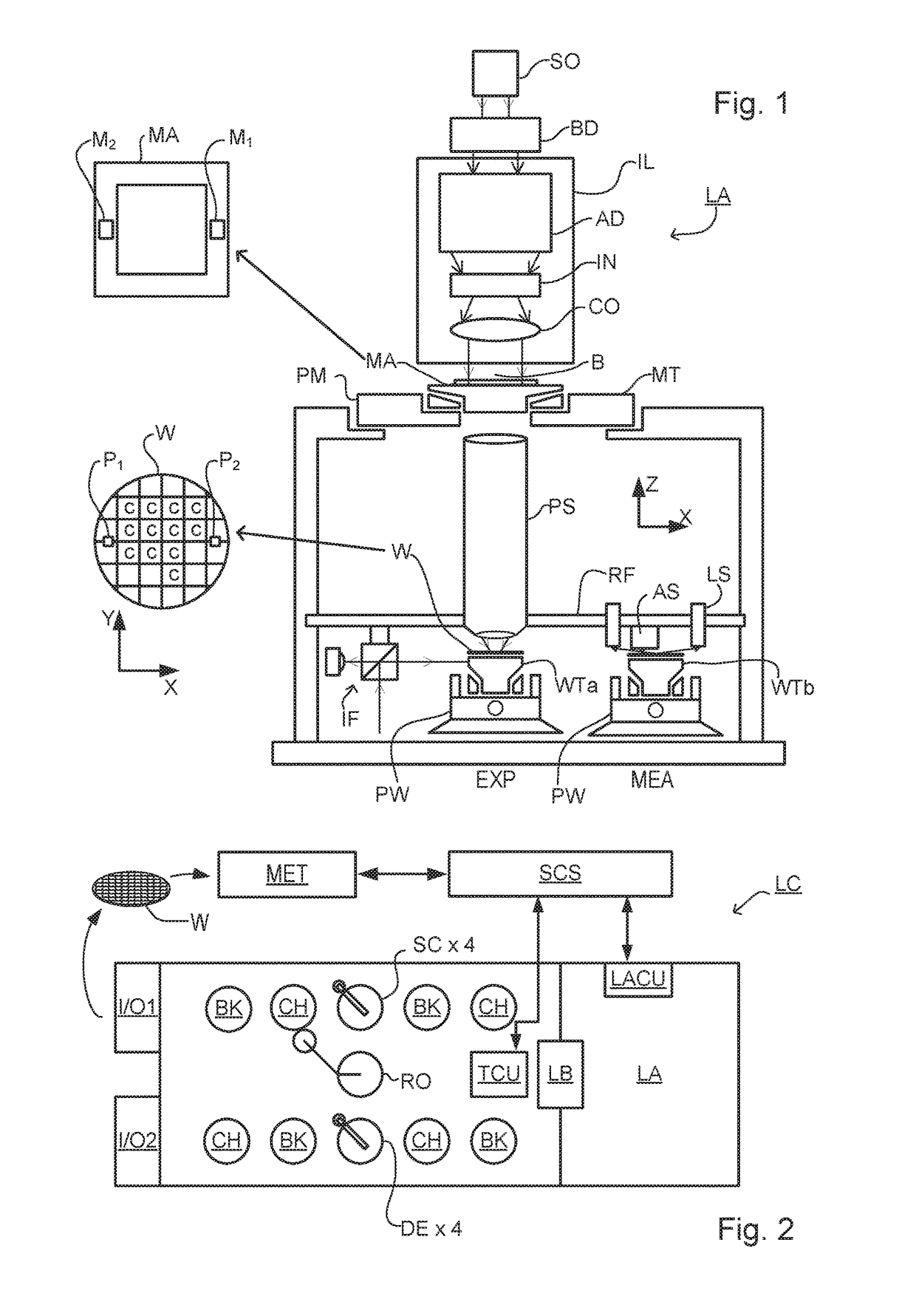
[0027]FIG. 1 schematically depicts a lithographic apparatus LA. The apparatus includes an illumination system (illuminator) IL configured to condition a radiation beam B (e.g., UV radiation or DUV radiation), a patterning device support or support structure (e.g., a mask table) MT constructed to support a patterning device (e.g., a mask) MA and connected to a first positioner PM configured to accurately position the patterning device in accordance with certain parameters; two substrate tables (e.g., a wafer table) WTa and WTb each constructed to hold a substrate (e.g., a resist coated wafer) W and each connected to a second positioner PW configured to accurately position the substrate in accordance with certain parameters; and a projection system (e.g., a refractive projection lens system) PS configured t...


PUM

PropertyMeasurementUnit
wavelengthsaaaaaaaaaa
wavelength differenceaaaaaaaaaa

Abstract

Disclosed is a method of monitoring a lithographic process parameter, such as focus and / or dose, of a lithographic process. The method comprises acquiring a first and a second target measurement using respectively a first measurement configuration and a second measurement configuration, and determining the lithographic process parameter from a first metric derived from said first target measurement and said second target measurement. The first metric may be difference. Also disclosed are corresponding measurement and lithographic apparatuses, a computer program and a method of manufacturing devices.

Description

BACKGROUND[0001]Field of the Invention[0002]The present invention relates to inspection apparatus and methods usable, for example, to perform metrology in the manufacture of devices by lithographic techniques. The invention further relates to such methods for monitoring a parameter such as focus and / or dose during or following a lithographic process.[0003]Background Art[0004]A lithographic apparatus is a machine that applies a desired pattern onto a substrate, usually onto a target portion of the substrate. A lithographic apparatus can be used, for example, in the manufacture of integrated circuits (ICs). In that instance, a patterning device, which is alternatively referred to as a mask or a reticle, may be used to generate a circuit pattern to be formed on an individual layer of the IC. This pattern can be transferred onto a target portion (e.g., including part of, one, or several dies) on a substrate (e.g., a silicon wafer). Transfer of the pattern is typically via imaging onto a...

Claims


Application Information

Patent Timeline
Patent Type & Authority Patents(United States)
IPC IPC(8): G01B11/04G01B11/27G01B11/02G03F7/20G03B27/74G03B27/32G03C5/00
CPCG03F7/70633G01B11/02G01B11/272G03F7/70625G03F7/70641G01B2210/56
Inventor STAALS, FRANKLUIJTEN, CARLO CORNELIS MARIAHINNEN, PAUL CHRISTIAANVAN OOSTEN, ANTON BERNHARD
Owner ASML NETHERLANDS BV
Features
  • R&D
  • Intellectual Property
  • Life Sciences
  • Materials
  • Tech Scout
  • Unparalleled Data Quality
  • Higher Quality Content
  • 60% Fewer Hallucinations
Learn More