
Static timing analysis with improved accuracy and efficiency

a timing analysis and accuracy technology, applied in the field of static timing analysis, can solve the problems of overestimation of delays, unstable circuit behavior, pessimism, etc., and achieve the effects of reducing runtime, improving accuracy, and reducing pessimism

Active Publication Date: 2018-06-19
SYNOPSYS INC
View PDF15 Cites 3 Cited by
  • Summary
  • Abstract
  • Description
  • Claims
  • Application Information

AI Technical Summary

Benefits of technology

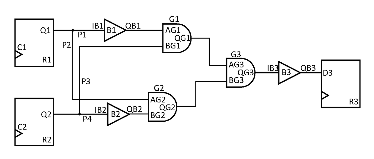
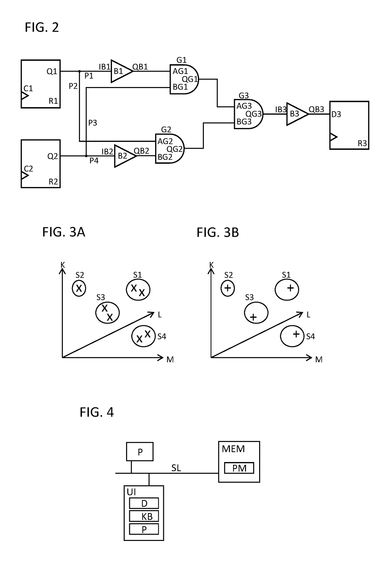
The present invention is about an improved technique for analyzing the timing of signals in a circuit design. This technique uses a graph of the circuit design to determine the arrival times of signals, but with reduced accuracy sacrifice compared to traditional methods. By merging timing signals from different parts of the circuit, the analysis is made faster but with a small loss of accuracy. This technique allows for more accurate timing computations with reduced runtime compared to previous methods. The analysis is done by defining subsets of timing signals that meet certain conditions, such as minimizing the size of the bounding box or maximizing accuracy. This invention improves the accuracy and efficiency of analyzing circuits and helps to ensure the proper functioning of timing paths.

Problems solved by technology

The difference between arrival and required time may be measured as slack, wherein a negative slack means an arrival time of the respective timing signal violates the respective required time and may lead to unstable circuit behavior.
GBA may combine information from different timing paths which may lead to overestimation of delays and hence a pessimistic slack.
This may unfortunately lead to an overestimation in the number of violating paths in the circuit design.
Unfortunately, analyzing all timing paths is a problem of exponential complexity in the size of the circuit.
Thus, performing PBA on an entire circuit may be infeasible for large circuits due to a large runtime and / or memory overhead.

Method used


Image

  • Static timing analysis with improved accuracy and efficiency
  • Static timing analysis with improved accuracy and efficiency
  • Static timing analysis with improved accuracy and efficiency

Examples


Embodiment Construction

[0065]FIG. 1 shows a simplified representation of an illustrative design flow for designing an electronic circuit in particular an integrated circuit (IC). An implementation of a method according to the improved concept may for example be embedded within such design flow. However, an implementation of a method according to the improved concept may also be utilized within another design flow or independently from a design flow.

[0066]At a high level, the process starts with the product idea (step 100) and is realized in an electronic design automation (EDA) software design process (step 110). When the design is finalized, it can be taped-out (step 127). At some point after tape-out, the fabrication process (step 150) and packaging and assembly processes (step 160) occur, resulting ultimately in finished IC chips (result 170).

[0067]The EDA software design process (step 110) itself is composed of a number of steps 112-130, shown in linear fashion for simplicity. In an actual integrated ...


PUM


Abstract

A method for performing static timing analysis of an integrated circuit design, wherein at least two timing paths share a shared node comprises propagating along the at least two timing paths a plurality of timing signals characterized by a set of timing parameters and determining respective values of the timing parameters at the shared node. Subsets of timing signals are defined based on relations between the determined parameter values of different timing signals. For each of the subsets representative parameter values are identified and a merged timing signal is propagated from the shared node at least partially along the at least two timing paths. Therein the merged timing signal has at the shared node the representative parameter values of the subset. The method also comprises generating timing data based on the merged timing signals and storing the timing data.

Description

BACKGROUND OF THE INVENTION[0001]The invention relates to static timing analysis (STA) in particular to STA with improved accuracy, in particular improved accuracy with respect to graph-based static timing analysis (GBA), and improved efficiency, in particular improved efficiency with respect to path-based static timing analysis (PBA).[0002]Current integrated circuit, IC, designs, may include an extremely large number of cells such as logic gates and synchronous or sequential devices connected by interconnects. The synchronous or sequential devices include flip-flops and latches.[0003]STA, for example, in the course of electronic design automation (EDA) is tasked with analyzing a circuit design to determine if timing constraints are met, for example whether all timing signals arrive at constrained cells or interconnects of the circuit design within a respective required time. The difference between arrival and required time may be measured as slack, wherein a negative slack means an...

Claims


Application Information

Patent Timeline
Patent Type & Authority Patents(United States)
IPC IPC(8): G06F17/50
CPCG06F17/5081G06F17/5036G06F30/3312G06F30/398G06F2119/12G06F30/367
Inventor WRIXON, ADRIANBELOV, ANTONKELLER, MAURICEMOLONEY, RICHARDDADHEECH, HIMANSHU
Owner SYNOPSYS INC
Learn More