Magnetic drive devices, and related systems and methods

a magnetic drive and drive device technology, applied in the direction of rotating magnets, dynamo-electric brakes/clutches, mechanical energy handling, etc., can solve the problem that conventional magnetic drive devices generally provide a relatively low torque, or voltage, outpu

Active Publication Date: 2018-06-26
NAT OILWELL VARCO LP
View PDF27 Cites 108 Cited by
  • Summary
  • Abstract
  • Description
  • Claims
  • Application Information

AI Technical Summary

Problems solved by technology

Conventional magnetic drive devices, however, generally provide a relatively low torque, or voltage, output due to the limits on magnetic and electrical stresses that can be used.

Method used


Image

  • Magnetic drive devices, and related systems and methods
  • Magnetic drive devices, and related systems and methods
  • Magnetic drive devices, and related systems and methods

Examples


Embodiment Construction

[0040]Reference will now be made in detail to various exemplary embodiments of the present disclosure, examples of which are illustrated in the accompanying drawings. Wherever possible, the same reference numbers will be used throughout the drawings to refer to the same or like parts.

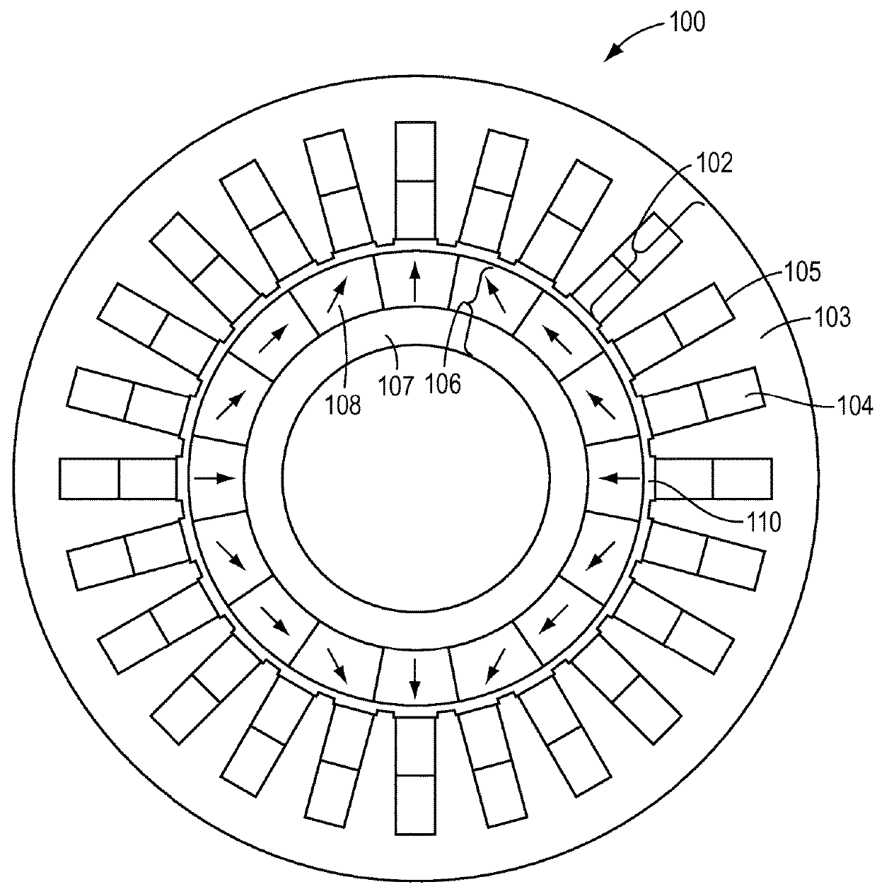
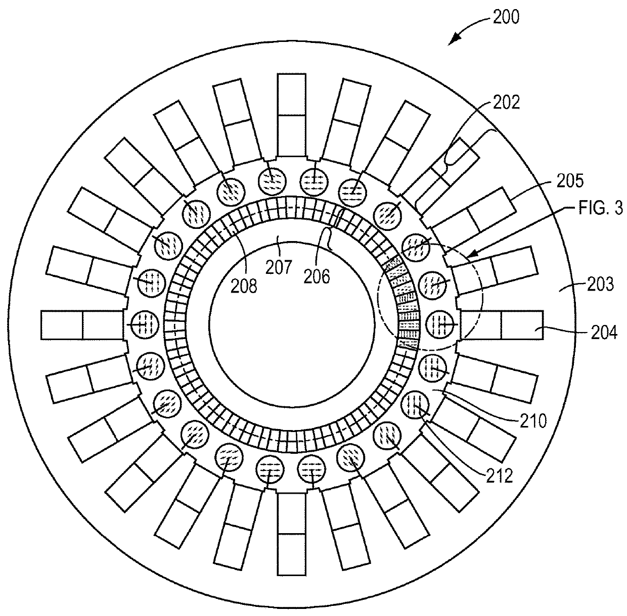
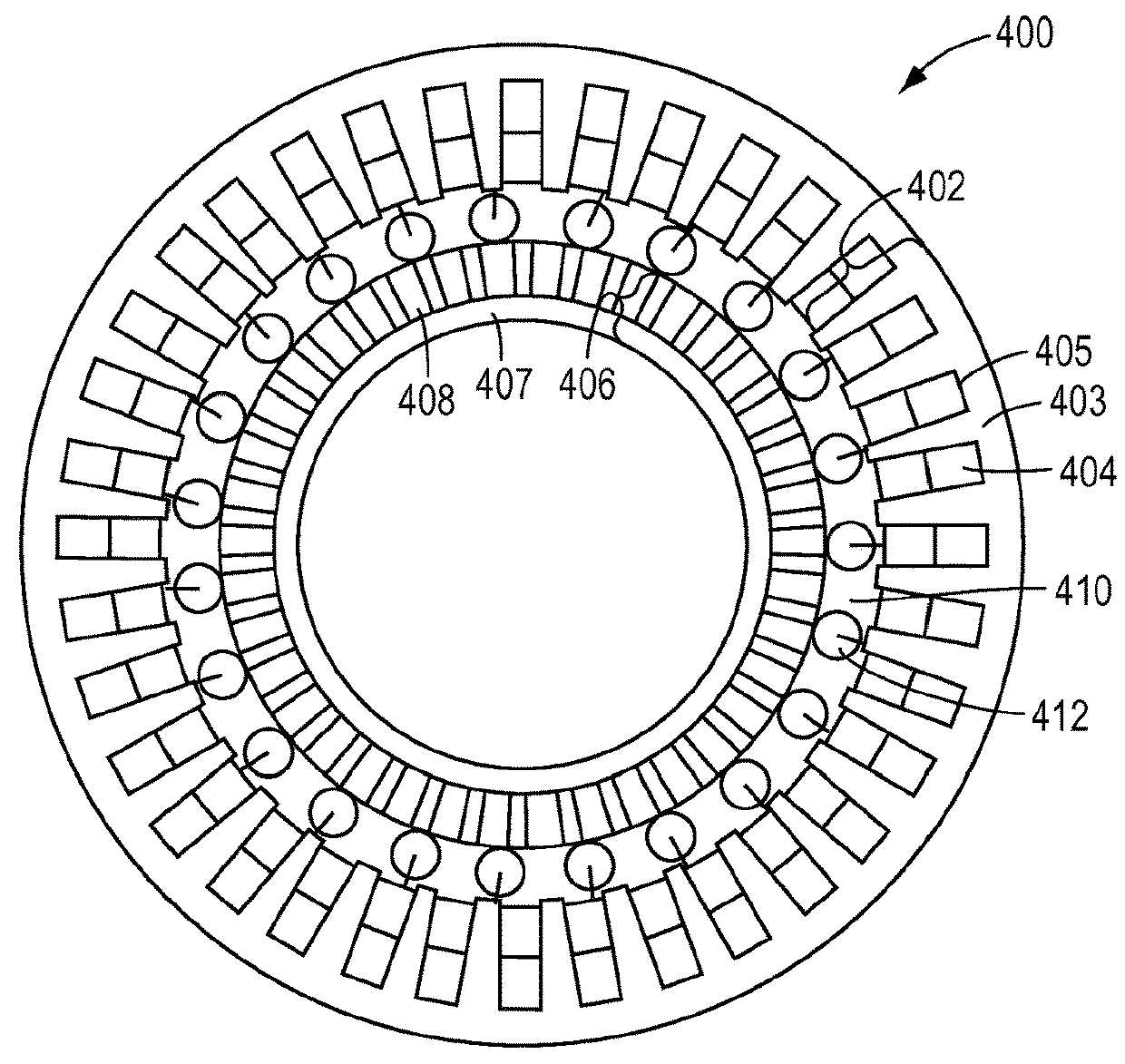
[0041]Various exemplary embodiments of the present disclosure contemplate magnetic drive devices, such as, for example, permanent magnet motors and generators, that have a reduced magnet volume compared to a conventional permanent magnet motor but with increased torque or voltage production. Various embodiments of the present disclosure contemplate, for example, magnetic drive devices comprising a plurality of free-spinning interpole elements positioned in an air gap between a stator and rotor, wherein the plurality of interpole elements harmonically couple the poles of the stator and rotor and provide a magnetomotive force (MMF) that amplifies the magnetic flux transferred between the stator and rotor....


PUM


Abstract

A magnetic drive device may comprise a stator comprising a plurality of windings for generating a first number of magnetic pole pairs and a rotor comprising a plurality of permanent magnets for generating a second number of magnetic pole pairs that differs from the first number of magnetic pole pairs. The magnetic drive device may further comprise a plurality of free-spinning interpole elements disposed within an air gap between the stator and the rotor. The interpole elements may produce a magnetomotive force and harmonically couple the magnetic pole pairs of the stator with the magnet pole pairs of the rotor.

Description

CROSS-REFERENCE TO RELATED APPLICATIONS[0001]This is a national stage application of PCT / US2013 / 028679, filed internationally on Mar. 1, 2013, which claims priority to U.S. Provisional Patent Application No. 61 / 606,305, filed Mar. 2, 2012 and entitled “Integrated Motor-Gear Using Spinning Magnets;” U.S. Provisional Patent Application No. 61 / 697,173, filed Sep. 5, 2012 and entitled “Magnetic Drive Devices, and Related Systems and Methods;” and U.S. Provisional Patent Application No. 61 / 653,353, filed May 30, 2012 and entitled “Oil Field Magnetic Drivers and Method of Using Same,” each of which is incorporated by reference herein in its entirety.TECHNICAL FIELD[0002]The present disclosure relates generally to magnetic drive devices, such as, for example, permanent magnet motors and generators, and related systems and methods. More particularly, the present disclosure relates to direct-drive permanent magnet motors that provide an increased torque output.INTRODUCTION[0003]The section h...

Claims


Application Information

Patent Timeline
Patent Type & Authority Patents(United States)
IPC IPC(8): H02K21/12H02K21/02H02K16/02E21B4/00H02K49/10H02K7/11
CPCH02K21/12E21B4/00H02K49/102H02K16/02H02K21/021H02K7/11
Inventor DAVEY, KENT R.CARDELLINI, DAVIDSWIONTEK, CLIFF A.
Owner NAT OILWELL VARCO LP
Why Eureka
Try Eureka