Mid-section of a can-annular gas turbine engine to introduce a radial velocity component into an air flow discharged from a compressor of the mid-section

a gas turbine engine and radial velocity technology, applied in the direction of machines/engines, stators, liquid fuel engines, etc., can solve the problems of fluid friction induced pressure loss and flow turbulen

Inactive Publication Date: 2018-07-03
SIEMENS ENERGY INC
View PDF28 Cites 2 Cited by
  • Summary
  • Abstract
  • Description
  • Claims
  • Application Information

AI Technical Summary

Benefits of technology

[0010]The present inventors have recognized that significant improvements in the operating efficiency, cost efficiency and / or cooling efficiency of a can annular gas turbine engine may be obtained by innovation in the design of the mid-section of the engine. The inventors have recognized that the movement of air from the compressor section to the combustor section in a can-annular gas turbine engine is a generally unstructured, chaotic process. Compressed air produced by the compressor section is directed into the annular chamber 15 and is allowed to find its path of least resistance around various structural obstacles and into one of the respective combustor heads 18. As a result, the flow experiences turbulence and fluid friction induced pressure losses. The present inventors have recognized that an improved engine mid-section design can minimize such losses, thereby providing improved overall engine performance. In addition, the present inventors have recognized that an improved engine mid-section design can also minimize losses associated with cooling the mid-section during operation, as well as lowering the manufacturing cost of the mid-section.
[0011]The air flow 11 experiences aerodynamic loss based on a total angle of rotation while traveling from the compressor section 12 to one of the combustor heads 18. The last stationary vane 26 and outlet guide vane 28 collectively rotate the air flow 11 by an initial absolute tangential swirl angle to remove the initial absolute tangential swirl angle that is imparted by the rotating blades 24, such as 45 degrees, to align the air flow 11 in a downstream longitudinal direction 68 upon entering the axial diffuser 14. In addition to the initial absolute tangential swirl angle rotation, upon exiting the diffuser 14 and entering the chamber 15, the air flow 11 experiences two 180 degree rotations: a first approximate 180 degree rotation to orient the air flow 11 from an initial downstream longitudinal direction 68 to an upstream longitudinal direction to travel longitudinally backward to a respective combustor head 18, and a second approximate 180 degree rotation at the combustor head 18 to direct the air flow 11 into an inlet of the combustor head 18. Accordingly, the air flow 11 undergoes a total rotation of approximately 400 degrees while traveling from the compressor section 12 to one of the combustor heads 18, and most of this rotation is accomplished in the unstructured environment of the chamber 15. The present inventors have recognized that the aerodynamic efficiency of the air flow from the compressor section to the respective combustor head can be enhanced by reducing this total rotation of the air and / or controlling the rotation process more precisely. For example, a radial velocity component may be introduced to the air flow at the diffuser outlet, such that the air flow is either a mixed-flow (which has combined longitudinal, tangential and radial velocity components) or a radial flow (which has a substantially radial velocity component) at the diffuser outlet. By introducing the radial velocity component to the air flow at the diffuser outlet, the required total angle of rotation within the chamber 15 will be decreased, and the aerodynamic efficiency of the air flow from the compressor section to the respective combustor head would be enhanced. The mixed-flow or radial flow may be initiated in the compressor section, in the diffuser, or at an interface between the compressor section and the diffuser, in various embodiments.
[0012]As discussed above, the last stage vane and outlet guide vane of a prior art can-annular gas turbine engine 10 are provided to eliminate the initial tangential swirl angle of approximately 45 degrees that is imparted by the rotating compressor blades 24, so that the air flow is directed into the chamber 15 along a downstream longitudinal direction (0 degree tangential swirl angle). The present inventors have recognized that some transition designs, such as the trans-vane design discussed above in FIG. 2, require a final absolute tangential swirl angle (with respect to the longitudinal direction 68) to be output from the transition 20′ to the first stage blade 49′ of the turbine section 48′ which is greater than the initial absolute tangential swirl angle generated by the last stage blade of the compressor section. For example, in an exemplary embodiment, a trans-vane design requires a final absolute tangential swirl angle of 70 degrees to the first stage blade 49′ of the turbine section 48′, in excess of the initial absolute tangential swirl angel of 45 degrees off the last stage blade 24 of the compressor section. The present inventors have recognized that it would be advantageous to maintain and then augment the initial absolute tangential swirl angle off the last stage blade of the compressor section rather than the prior art practice of eliminating it through the last stage compressor vane 26 and outlet guide vane 28 and replacing it through the transition 20′ to the first stage blade 49′ of the turbine section 48′. The inventors have recognized that the initial absolute tangential swirl angle off the last stage blade of the compressor section can be increased by an offset angle through a trans-vane transition so that the absolute tangential swirl angle of the air flow output from the trans-vane transition fulfills the required final absolute tangential swirl angle incident on the first stage blade 49′. This offset angle through the transition may be 25 degrees, for example, which is additive to the 45 degree angle provided by the last stage compressor blades 24 to achieve a required 70 degree tangential angle at the first stage turbine blade 49′, thereby eliminating the need for the last stage compressor vane 26 and outlet guide vane 28. By maintaining or supplementing the initial absolute tangential swirl angle of the air flow off the last stage blade of the compressor section, the air flow can be passed from the compressor outlet to a respective combustor head with a substantially reduced total angle of rotation when compared to the conventional design, thereby enhancing the aerodynamic efficiency of the midframe portion of the gas turbine engine.
[0014]The conventional design of the midframe portion 13 of the gas turbine engine 10 features several components aligned along the axis of the compressor section, such as the last stage blade 24, the last stage vane 26, the outlet guide vane 28 and the axial diffuser 14, for example. The amount of material used to form these components and / or the longitudinal length of these components along the midframe portion of the gas turbine engine collectively contribute to the cost of manufacturing the gas turbine engine. In accordance with an aspect of the invention when either mixed-flow or radial flow of air is provided from a diffuser outlet, one or more of the prior art axial compressor stages could be replaced with a newly designed last stage blade which initiates a mixed-flow or radial flow to be outputted from the compressor section. Thus, by replacing one or more axial compressor stages with a mixed-flow or radial flow at the compressor outlet, the longitudinal length of components and / or the amount of material used to form the midframe portion of the engine is reduced, which lowers the cost of manufacturing the midframe portion of the turbine engine.

Problems solved by technology

As a result, the flow experiences turbulence and fluid friction induced pressure losses.

Method used


Image

  • Mid-section of a can-annular gas turbine engine to introduce a radial velocity component into an air flow discharged from a compressor of the mid-section
  • Mid-section of a can-annular gas turbine engine to introduce a radial velocity component into an air flow discharged from a compressor of the mid-section
  • Mid-section of a can-annular gas turbine engine to introduce a radial velocity component into an air flow discharged from a compressor of the mid-section

Examples


Embodiment Construction

[0036]The description below is organized into two major sections: 1) a description of alternatives for generating mixed flow or radial flow in the turbine midsection, and 2) a description of alternatives for delivering the mixed flow or radial flow to the combustor head-end.

1. Initiation of Mixed-Flow or Radial Flow

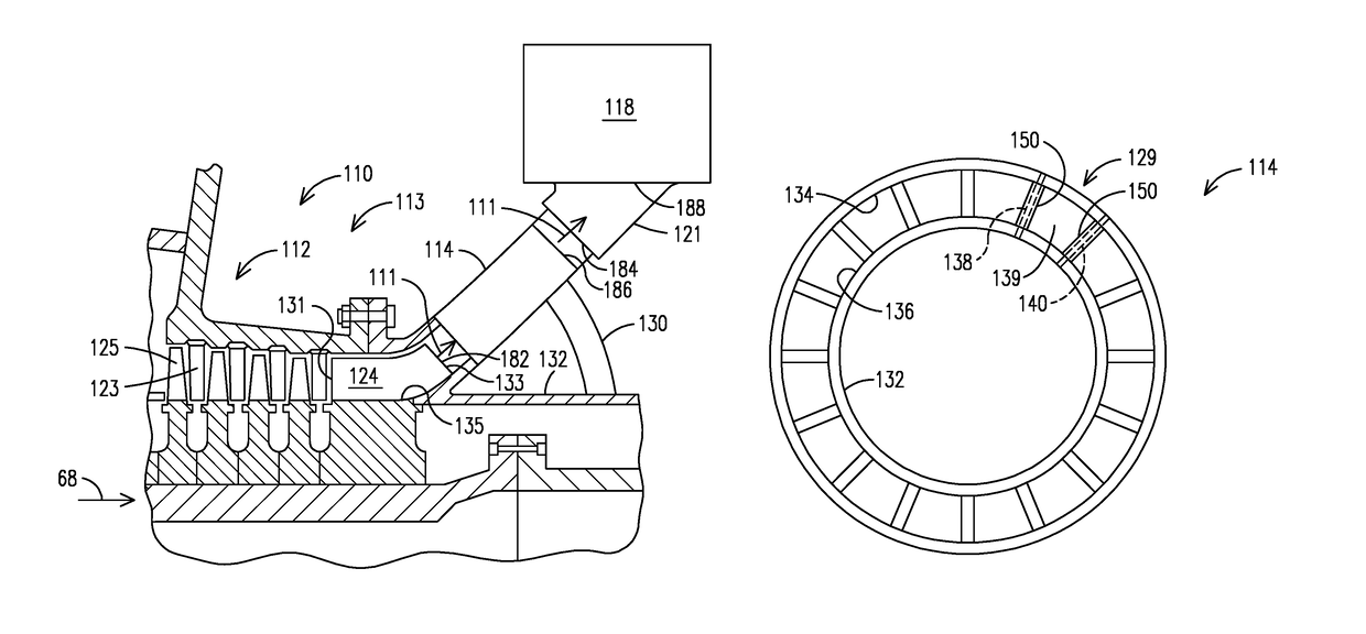
[0037]As discussed above, the inventors of the present invention recognized that an improved midframe portion of the gas turbine engine features initiating a mixed air flow (axial, tangential plus radial flow velocities) or a completely radial air flow from the diffuser outlet. By initiating the mixed-air flow or radial air flow from the diffuser outlet, the air flow passes from the diffuser outlet to the combustor head inlet while undergoing a reduced total angle of rotation when compared to the air flow with the conventional midframe portion. The embodiments of the present invention discussed below in FIGS. 4-8 introduce various midframe designs in which the mixed air f...


PUM


Abstract

A midframe portion (113) of a gas turbine engine (110) is provided, including a compressor section (112) with a last stage blade (124). The compressor section (112) is configured to introduce a radial velocity component into an air flow (111) such that the air flow is discharged from the compressor section (112) at a mixed direction based on a combined longitudinal velocity component and radial velocity component. The midframe portion (113) further includes a manifold (121) to directly couple the air flow from an outlet of the compressor section (112) to an inlet of a respective combustor head (118) of the gas turbine engine (110).

Description

STATEMENT REGARDING FEDERALLY SPONSORED DEVELOPMENT[0001]Development for this invention was supported in part by Contract No. DE-FC26-05NT42644, awarded by the United States Department of Energy. Accordingly, the United States Government may have certain rights in this invention.FIELD OF THE INVENTION[0002]The invention relates to can-annular gas turbine engines, and more specifically, to a midframe portion of a can-annular gas turbine engine.BACKGROUND OF THE INVENTION[0003]A conventional midframe design for a can-annular gas turbine engine is discussed in U.S. Pat. No. 7,721,547 (“'547 patent”), assigned to the assignee of the present invention, which is incorporated by reference herein. FIG. 1 of the '547 patent is reproduced as FIG. 1 herein, and illustrates a cross-section through a midframe portion 13 of a conventional can-annular gas turbine engine 10. The major components of the gas turbine engine 10 are a compressor section 12, a combustion section 16 and a turbine section ...

Claims


Application Information

Patent Timeline
Patent Type & Authority Patents(United States)
IPC IPC(8): F02C3/14F01D9/04
CPCF02C3/14F01D9/041F04D29/44F04D29/54
Inventor RODRIGUEZ, JOSE L.
Owner SIEMENS ENERGY INC
Why Eureka
Try Eureka