Mid-section of a can-annular gas turbine engine to introduce a radial velocity component into an air flow discharged from a compressor of the mid-section

a gas turbine engine and radial velocity technology, applied in the direction of machines/engines, stators, liquid fuel engines, etc., can solve the problems of fluid friction induced pressure loss and flow turbulen

Inactive Publication Date: 2013-08-29
SIEMENS ENERGY INC
View PDF23 Cites 11 Cited by
  • Summary
  • Abstract
  • Description
  • Claims
  • Application Information

AI Technical Summary

Problems solved by technology

As a result, the flow experiences turbulence

Method used


Image

  • Mid-section of a can-annular gas turbine engine to introduce a radial velocity component into an air flow discharged from a compressor of the mid-section
  • Mid-section of a can-annular gas turbine engine to introduce a radial velocity component into an air flow discharged from a compressor of the mid-section
  • Mid-section of a can-annular gas turbine engine to introduce a radial velocity component into an air flow discharged from a compressor of the mid-section

Examples


Embodiment Construction

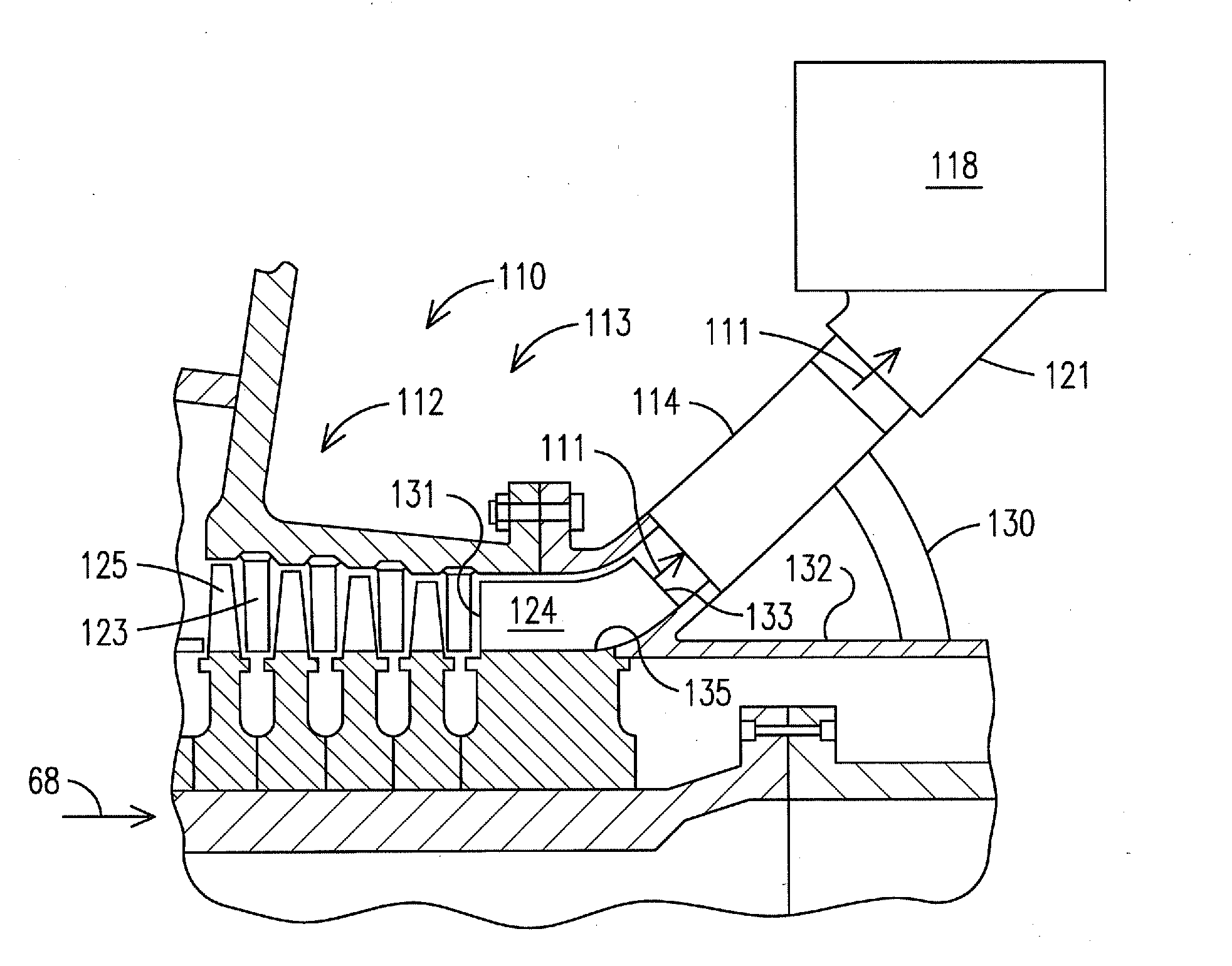
[0036]The description below is organized into two major sections: 1) a description of alternatives for generating mixed flow or radial flow in the turbine midsection, and 2) a description of alternatives for delivering the mixed flow or radial flow to the combustor head-end.

1. Initiation of Mixed-Flow or Radial Flow

[0037]As discussed above, the inventors of the present invention recognized that an improved midframe portion of the gas turbine engine features initiating a mixed air flow (axial, tangential plus radial flow velocities) or a completely radial air flow from the diffuser outlet. By initiating the mixed-air flow or radial air flow from the diffuser outlet, the air flow passes from the diffuser outlet to the combustor head inlet while undergoing a reduced total angle of rotation when compared to the air flow with the conventional midframe portion. The embodiments of the present invention discussed below in FIGS. 4-8 introduce various midframe designs in which the mixed air f...


PUM


Abstract

A midframe portion (113) of a gas turbine engine (110) is provided, including a compressor section (112) with a last stage blade (124). The compressor section (112) is configured to introduce a radial velocity component into an air flow (111) such that the air flow is discharged from the compressor section (112) at a mixed direction based on a combined longitudinal velocity component and radial velocity component. The midframe portion (113) further includes a manifold (121) to directly couple the air flow from an outlet of the compressor section (112) to an inlet of a respective combustor head (118) of the gas turbine engine (110).

Description

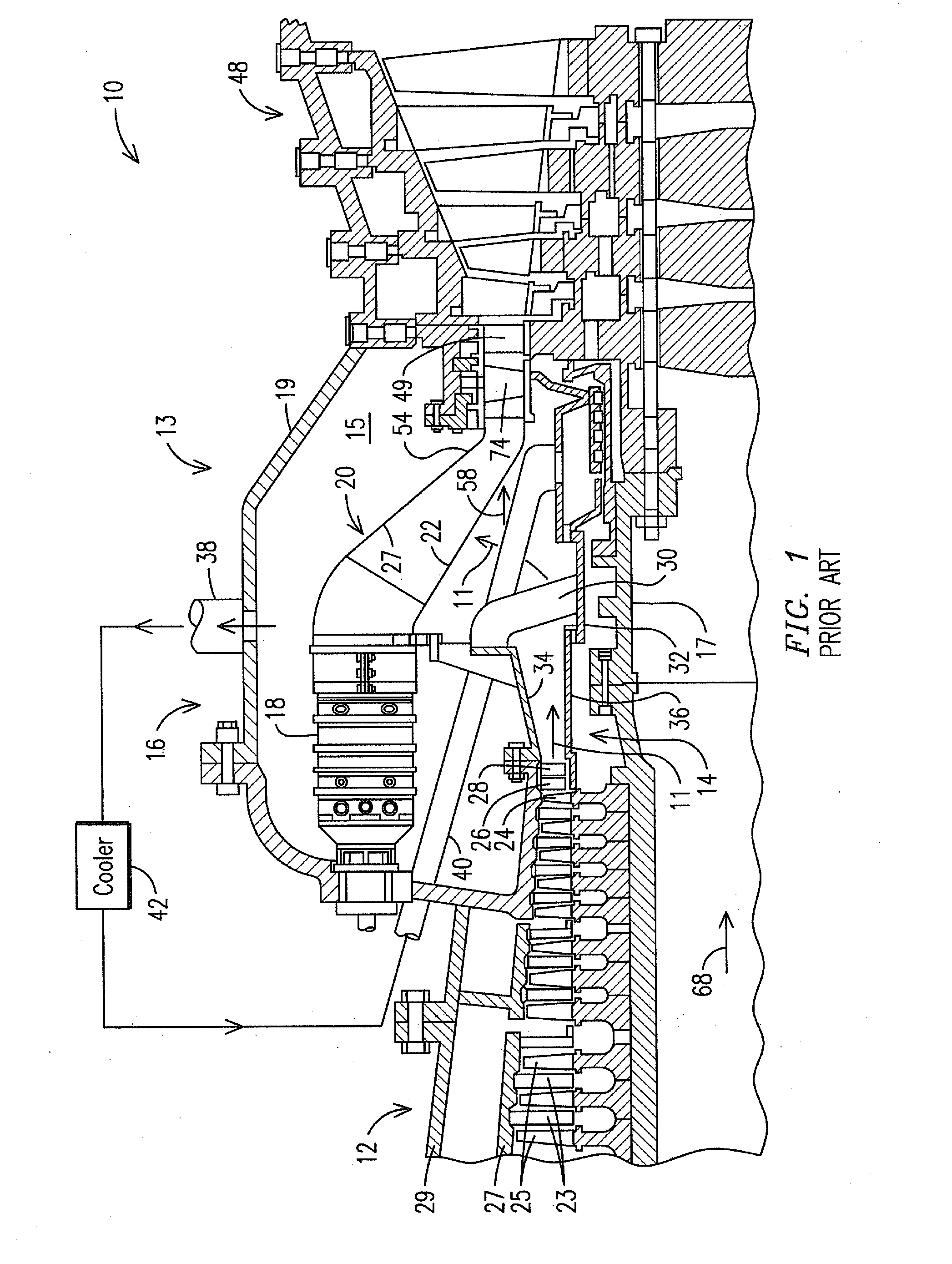
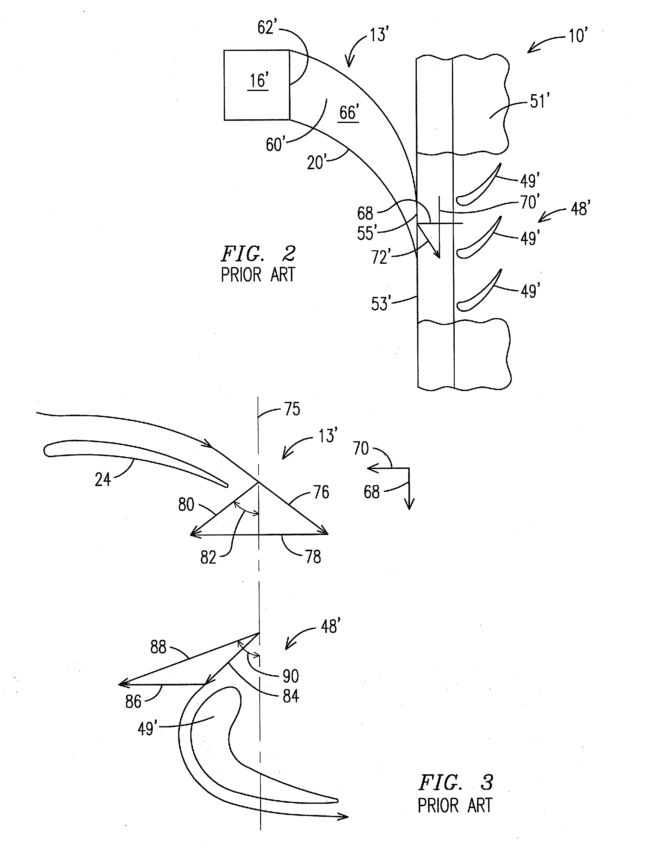
STATEMENT REGARDING FEDERALLY SPONSORED DEVELOPMENT[0001]Development for this invention was supported in part by Contract No. DE-FC26-05NT42644, awarded by the United States Department of Energy. Accordingly, the United States Government may have certain rights in this invention.FIELD OF THE INVENTION[0002]The invention relates to can-annular gas turbine engines, and more specifically, to a midframe portion of a can-annular gas turbine engine.BACKGROUND OF THE INVENTION[0003]A conventional midframe design for a can-annular gas turbine engine is discussed in U.S. Pat. No. 7,721,547 (“'547 patent”), assigned to the assignee of the present invention, which is incorporated by reference herein. FIG. 1 of the '547 patent is reproduced as FIG. 1 herein, and illustrates a cross-section through a midframe portion 13 of a conventional can-annular gas turbine engine 10. The major components of the gas turbine engine 10 are a compressor section 12, a combustion section 16 and a turbine section ...

Claims


Application Information

Patent Timeline
IPC IPC(8): F01D1/04
CPCF02C3/14F01D9/041F04D29/44F04D29/54
Inventor RODRIGUEZ, JOSE L.
Owner SIEMENS ENERGY INC
Why Eureka
Try Eureka