Internal combustion engine with coaxially aligned pistons

a technology of coaxial alignment and internal combustion engine, which is applied in the direction of combustion engine, reciprocating piston engine, positive displacement engine, etc., can solve the problems of contaminating the fuel air charge, excessive buildup of burned oil, and undesirable pressure increase within the oil filled crankcas

Active Publication Date: 2018-07-03
ALFADAN INC
View PDF13 Cites 2 Cited by
  • Summary
  • Abstract
  • Description
  • Claims
  • Application Information

AI Technical Summary

Benefits of technology

[0018]Before the present invention is disclosed and described, it is to be understood that the terminology used herein is for the purpose of describing particular embodiments only and is not intended to be limiting. The terms “a” or “an,” as used herein, are defined as one or more than one. The term “plurality,” as used herein, is defined as two or more than two. The term “another,” as used herein, is defined as at least a second or more. The terms “

Problems solved by technology

This passage of oil from the crankcase into the combustion chamber results in an excessive buildup of burned oil seen as a varnish buildup within the bottom end of the cylinders and the actual combustion side of the cylinder heads.
While the theory and principle of operation of the Bourke engine are such that this engine offers many advantages over some more conventional internal combustion engines, certain mechanical problems along with a custom non pump gas specific fuel mixture have been observed in Bourke type engines which have heretofore been built and tested, and these problems appear to have contributed to the apathy of engine builders toward the Bourke engine.
For one, given the fact that a substantial amount of fuel air pressure is present underneath the piston as it reaches bottom dead center, the sealing

Method used


Image

  • Internal combustion engine with coaxially aligned pistons
  • Internal combustion engine with coaxially aligned pistons
  • Internal combustion engine with coaxially aligned pistons

Examples


Embodiment Construction

[0037]While the specification concludes with claims defining the features of the invention that are regarded as novel, it is believed that the invention will be better understood from a consideration of the following description in conjunction with the drawing figures, in which like reference numerals are carried forward. It is to be understood that the disclosed embodiments are merely exemplary of the invention, which can be embodied in various forms.

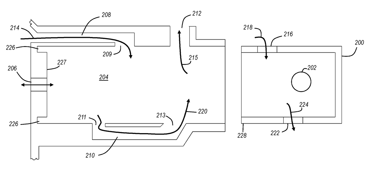
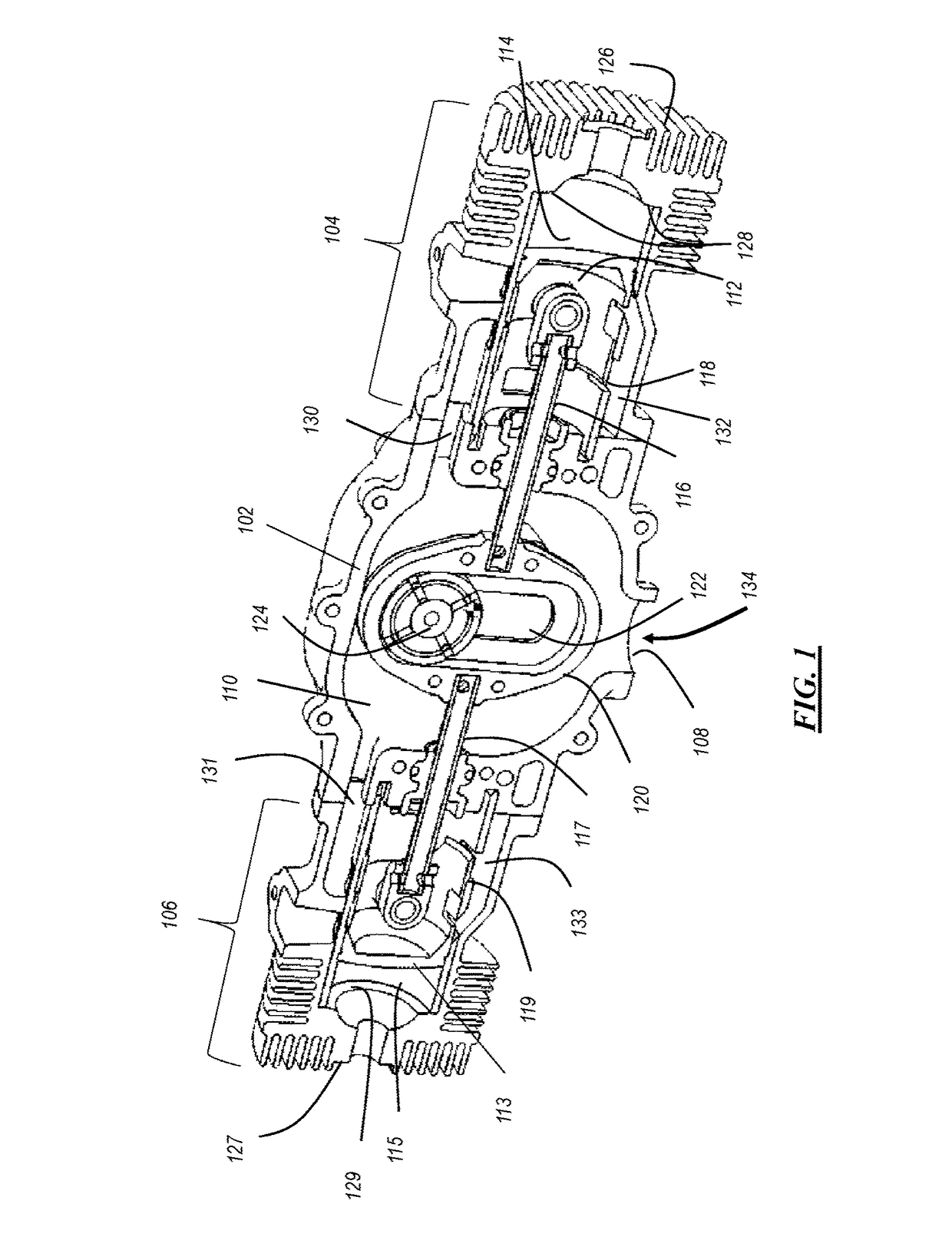
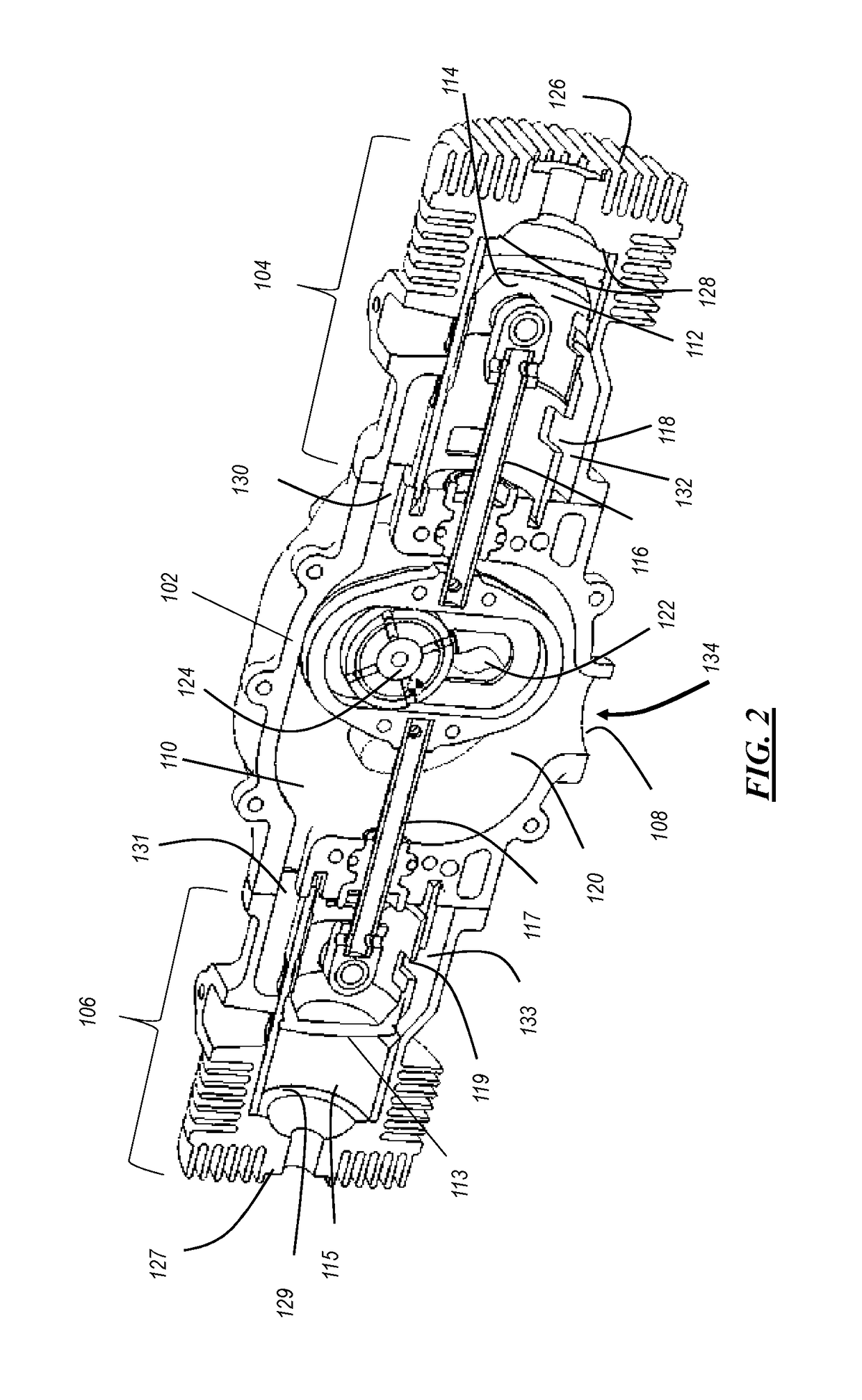
[0038]The present invention provides a novel and efficient internal combustion engine arranged in a free piston configuration. Embodiments of the invention provide an internal combustion engine that includes a crankcase having a crankcase chamber with a pair of longitudinally opposing cylinder units coupled on respective opposing sides of the crankcase. Each cylinder unit includes a cylinder therein, an intake channel from the crankcase chamber to a cylinder intake port in a side of the cylinder, a transfer channel from a lower cylinde...


PUM


Abstract

An internal combustion engine using a two stroke cycle includes a pair of opposing cylinder units, each of which are located on opposing sides of a crankcase. In each cylinder unit is a cylinder with a piston disposed in the cylinder. Each piston is coupled to a piston rod that is aligned along an axis that passes through the center of each cylinder bore. The piston rods pass through the crankcase wall into the crankcase chamber, and are further coupled to a yoke. Each cylinder unit has an intake channel from the crankcase chamber to a cylinder intake port in the cylinder. As the piston traverses its upstroke in its cylinder, it creates a vacuum under the piston. At the top of its stroke a piston intake port becomes aligned with the cylinder intake port, allow fuel to be drawn into the cylinder under the piston. As a result, a continuous vacuum is experienced in the crankcase without the need for mechanical valving arrangements.

Description

FIELD OF THE INVENTION[0001]The present invention relates generally to internal combustion engines, and more particularly to internal combustion engines in a free piston configuration.BACKGROUND OF THE INVENTION[0002]It is well known by persons familiar with the free piston engine that it is comprised of pairs of cylinders with each pair coaxially aligned and disposed back to back with the piston rods extending from the pistons reciprocating in each of these cylinders also coaxially aligned and being joined by a yoke. Perhaps the most well-known free piston engine arrangement is the so-called Bourke engine, named after Russel Bourke. In a free piston engine the center of the yoke is transversely slotted to receive the throw of a crank so that, as each pair of pistons and their yoke-joined piston rods reciprocate as a unit, the crank throw will not only be reciprocated with and in the direction of the yoke, but it will also reciprocate transversely in the yoke slot. Thereby, there is...

Claims


Application Information

Patent Timeline
IPC IPC(8): F02B75/24F02B25/06F02B25/08
CPCF02B75/243F02B25/06F02B25/08F02B2700/03F02B2275/40F01B1/08F02B75/005F01B7/00F01B9/023F02B75/24F02B75/246F02B75/32
Inventor ARAUJO, ALBERTO FRANCISCO
Owner ALFADAN INC
Why Eureka
Try Eureka