Absorber for a wind turbine

a technology for wind turbines and absorbers, which is applied in the direction of machines/engines, mechanical equipment, chemical equipment and processes, etc., can solve the problems of inability to secure or mount absorbing plates during initial installation or production of wind turbines, high installation costs of such types of absorbers, and inability to meet service and maintenance activities, etc., to achieve simple and cheap solution, low complexity, and simple design

Inactive Publication Date: 2018-07-03
SIEMENS GAMESA RENEWABLE ENERGY AS
View PDF7 Cites 0 Cited by
  • Summary
  • Abstract
  • Description
  • Claims
  • Application Information

AI Technical Summary

Benefits of technology

[0014]The absorber element according to the proposed solution has a low complexity and a simple design. The proposed absorber element can be secured / mounted during production of the wind turbine without hindering, e.g., the installation of rotor blades.
[0015]Thus, securing one or a number of absorber elements to a rotatable part within the interior of the wind turbine is a simple and cheap solution for absorbing any lubricant wasted inside the wind turbine. The rotatable part may be able to rotate about the same or approximately about the same rotation axis as a rotor hub or a generator of the wind turbine.
[0027]According to an embodiment, at least a part of the at least one hole and / or the at least one opening of the container is located at a side of the container closest to the at least one reinforcement plate or to the inner surface of the rotor hub. This allows easy access of wasted lubricant running past the container to the absorbing material located inside the container.

Problems solved by technology

Alternative energy sources have become much more necessary as fossil fuels are depleted and pollute the environment.
However, the installation of such kind of absorbing plates is expensive and not satisfying with regard to service and maintenance activities.
As a further disadvantage, such absorbing plates cannot be secured or mounted during initial installation or production of a wind turbine as they are hindering the installation of rotor blades during, e.g., erection of the wind turbine.

Method used


Image

  • Absorber for a wind turbine
  • Absorber for a wind turbine
  • Absorber for a wind turbine

Examples


Embodiment Construction

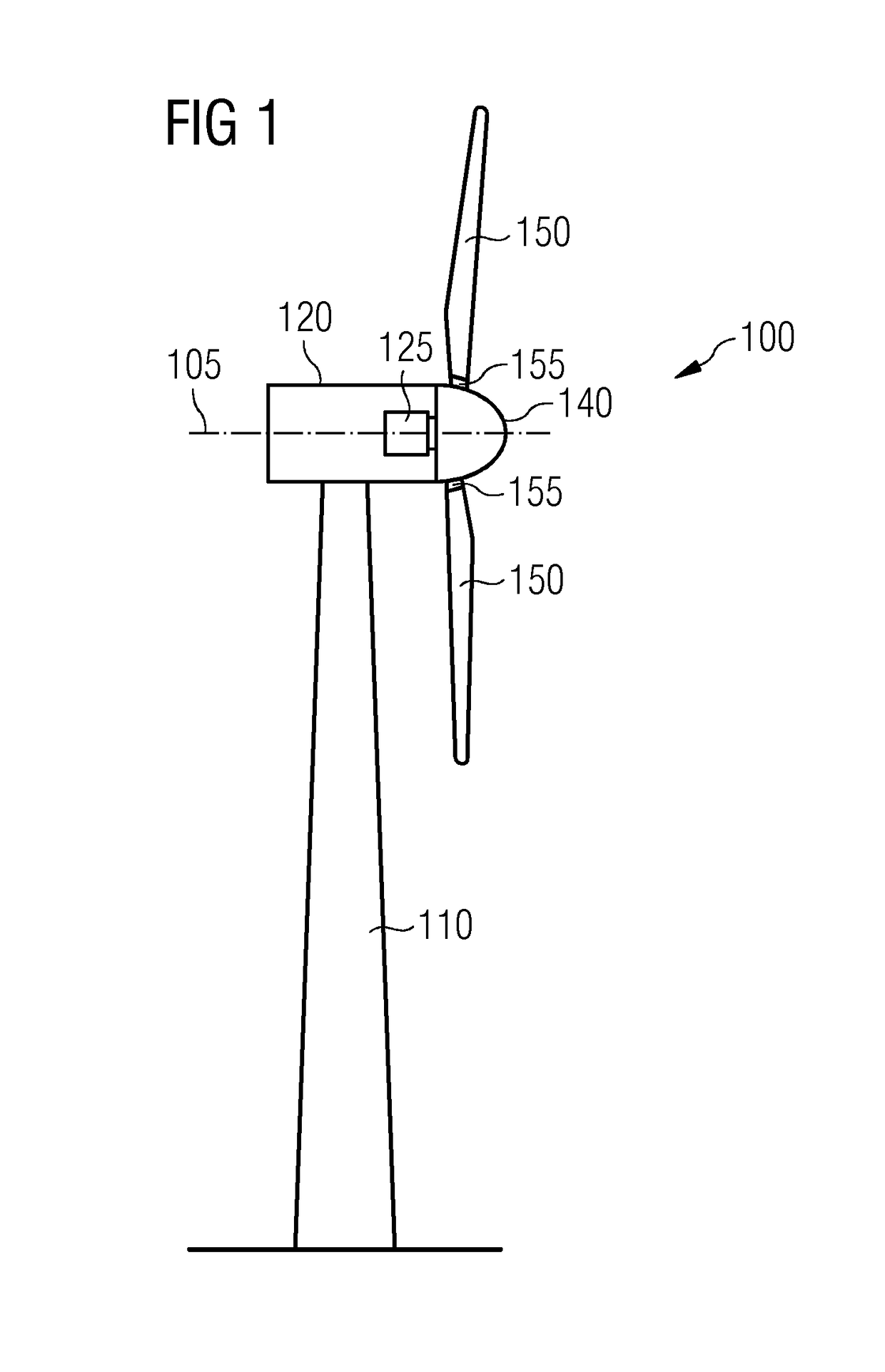
[0048]With reference to FIG. 1 an exemplary schematic overview of a wind turbine 100 is shown. The wind turbine 100 comprises a tower 110, a nacelle 120 and a rotor hub 140. The nacelle 120 is located on top of the tower 110. The rotor hub 140 comprises a number of wind turbine blades 150. The blades 150 may be rotatable mounted to the rotor hub 140 by respective blade bearings 155 allowing the blades 150 to be pitched into or out of the wind.

[0049]The rotor hub 140 is mounted to the nacelle 120 such, that it is able to rotate about a rotation axis 105. A generator 125 is located inside the nacelle 120. The wind turbine 100 can be, e.g., a direct drive wind turbine.

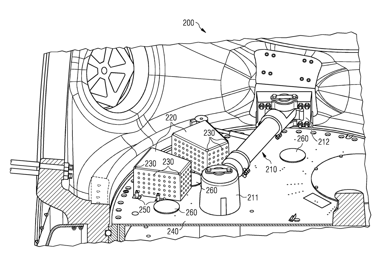
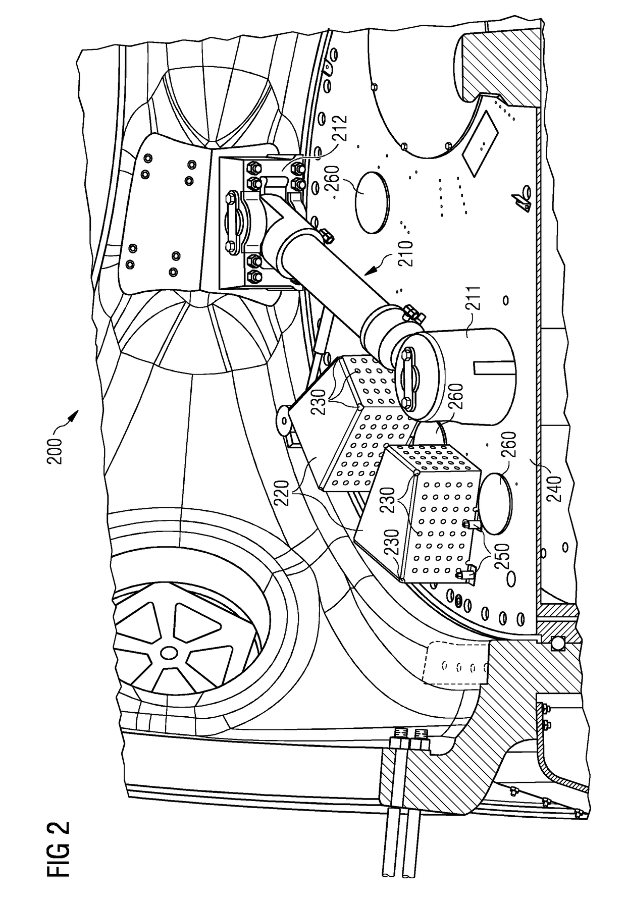
[0050]FIG. 2 illustrates a schematical view of an interior 200 of a rotor hub thereby showing an exemplary embodiment of the proposed solution. The interior 200 of the rotor hub represents a rotatable part of a wind turbine.

[0051]A hydraulic blade pitch system 210 is located in the interior 200 of the rotor hub, being att...


PUM


Abstract

A wind turbine including a rotatable part, at least one absorber element secured to the rotatable part within an interior of the wind turbine, the at least one absorber element at least partly comprising lubricant absorbing material, wherein the absorber element is configured to absorb emerging lubricant inside the wind turbine is provided. Further, a rotor hub for a wind turbine, an absorber element for a wind turbine and a method for maintaining a clean environment in a wind turbine is also provided.

Description

CROSS-REFERENCE TO RELATED APPLICATIONS[0001]This application claims priority to EP Application No. 14170346.2, having a filing date of May 28, 2014, the entire contents of which are hereby incorporated by reference.FIELD OF TECHNOLOGY[0002]The following relates to a wind turbine, a rotor hub for a wind turbine, an absorber element for a wind turbine and a method for maintaining a clean environment in a wind turbine.BACKGROUND[0003]Alternative energy sources have become much more necessary as fossil fuels are depleted and pollute the environment. Wind energy is one of the most cost effective of all types of renewable energy. However, to make wind a viable source of energy or electricity in particular careful design of wind-capturing machines is necessary. A variety of principles of physics are used to create wind turbines that can efficiently capture energy from the wind. Wind turbines can be onshore or offshore.[0004]A wind turbine typically includes a tower, a nacelle supported by...

Claims


Application Information

Patent Timeline
Patent Type & Authority Patents(United States)
IPC IPC(8): B08B1/00F03D7/02F03D1/06F03D80/70F03D9/25
CPCF03D7/0224B08B1/001F03D1/06F03D1/0691F03D80/70F03D9/25Y02E10/723F05B2260/406F05B2260/98Y02E10/721Y02E10/72F03D15/20
Inventor CARLSEN, PETER KAUFMANNEBBESEN, HENNINGLAURITSEN, TORBEN
Owner SIEMENS GAMESA RENEWABLE ENERGY AS
Why Eureka
Try Eureka