Structure for attaching pressure detector

a diaphragm and detector technology, applied in the direction of fluid pressure measurement, branching pipes, instruments, etc., can solve the problems of output and temperature characteristics changing before, and it is difficult to completely eliminate the diaphragm stress warping

Active Publication Date: 2018-07-03
COPAL ELECTRON CO LTD +1
View PDF20 Cites 6 Cited by
  • Summary
  • Abstract
  • Description
  • Claims
  • Application Information

AI Technical Summary

Benefits of technology

[0046]Since the present invention is so configured that the pressure receiving chamber is provided within the casing of the pressure detector, the diaphragm which is displaced depending on the pressure of the pressure receiving chamber is provided in the casing, a pipe on which a pressure introduction hole for communicating with the pressure receiving chamber is provided in the casing in a protruding state, a gasket presser is provided at the front end portion of the pipe, the gasket presser is inserted into an insertion hole of an attachment tool main body attached to a pipeline and the like and the front end face of the gasket presser is brought into contact with one end face of a gasket provided on the bottom face of the insertion hole, a split ring or U-shaped ring is brought into contact with the face opposite to the front end face of the gasket presser, and further the bonnet is inserted into the insertion hole of the attachment tool main body to tighten the same to the attachment tool main body side, whereby the gasket presser and the gasket are pressed via the split ring or U-shaped ring, and sealing portions are formed between one end face of the gasket and the bottom face of the insertion hole and between the other end face of the gasket and the front end face of the gasket presser, respectively, even when the distance between the gasket presser receiving the compressive force by the pipe in which the pressure introduction hole is formed and the diaphragm of the pressure detector is increased and the gasket presser received the compressive force, no component of the force is transmitted to the diaphragm.
[0047]As a result, in the present invention, no stress influence is exerted on the diaphragm even after the integration of the pressure detector into the attachment tool main body, and no change is made in the output and temperature characteristics before and after the attachment of the pressure detector to the attachment tool main body.
[0048]Moreover, in the present invention, even if the tightening force of the bonnet is reduced due to aged deterioration after the integration of the pressure detector to the attachment tool main body and the compressive force of the gasket presser is changed, the distance between the gasket presser which receives the compressive force and the diaphragm of the pressure detector is wide, and therefore there is no influence of the stress on the diaphragm, and the diaphragm is not affected by aged deterioration.
[0049]Furthermore, since the present invention is so configured that the split ring is divided into two parts along the diameter direction, and the bonnet is formed to be a cylindrical bonnet having an inner diameter which is larger than the outer diameter of the gasket presser and smaller than the outer diameter of the split ring, and the bonnet is removably screwed into an insertion hole of the attachment tool main body, even though the gasket presser having a diameter larger than the pipe is provided at the front end portion of the pipe of the pressure detector, the pressure detector can be integrated and fixed into the insertion hole of the attachment tool main body, allowing great convenience.

Problems solved by technology

However, in the structure for attaching the conventional pressure detector 30 mentioned above, when the pressure detector 30 is fixed to the insertion hole 40 of the attachment tool main body 39, it is difficult to completely eliminate the stress warping of the diaphragm 33, and there is the problem that the output and temperature characteristics change before and after the integration of the pressure detector 30 to the attachment tool main body 39.

Method used


Image

  • Structure for attaching pressure detector
  • Structure for attaching pressure detector
  • Structure for attaching pressure detector

Examples


Embodiment Construction

[0064]Embodiments of the present invention will be described below with reference to drawings.

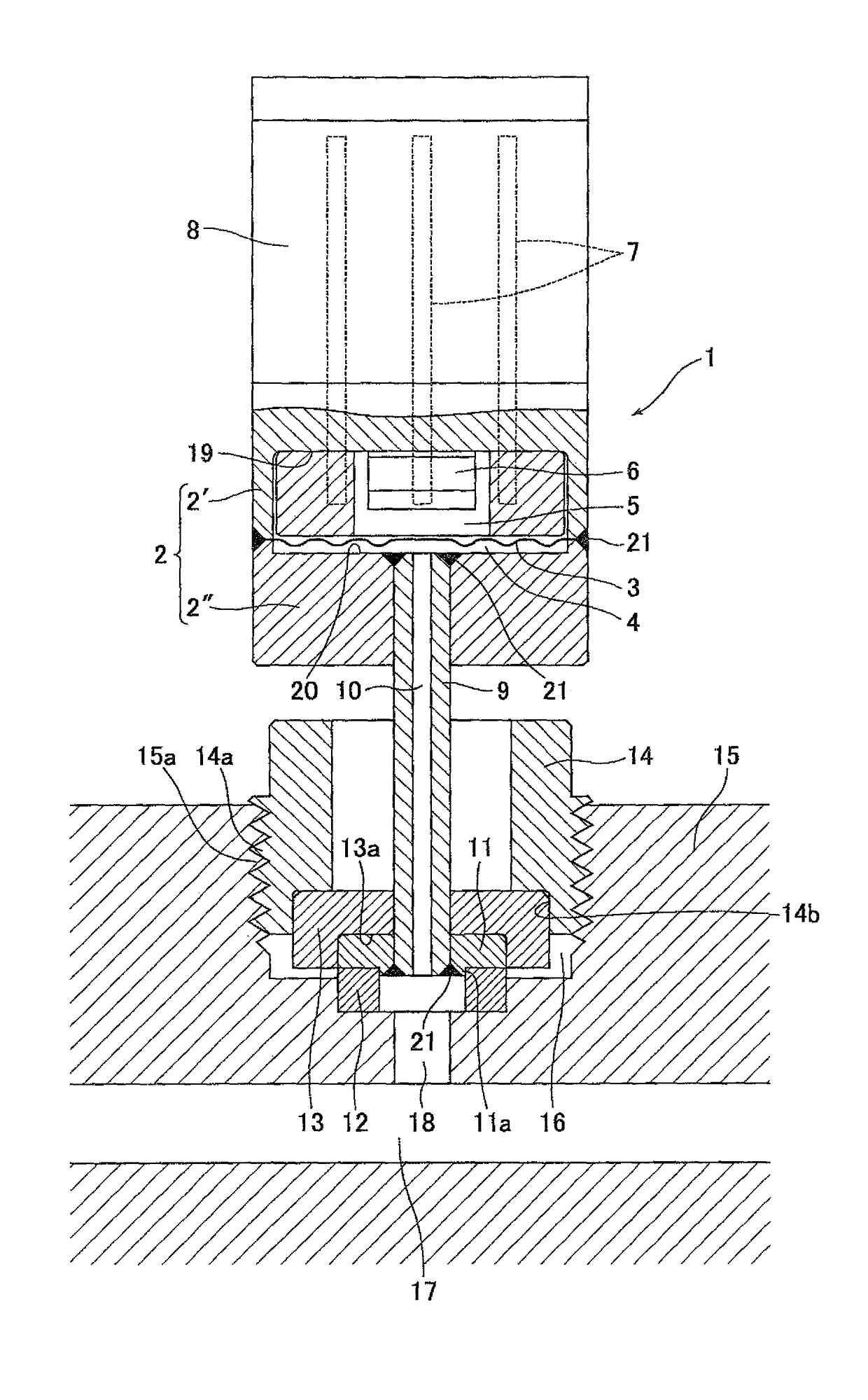
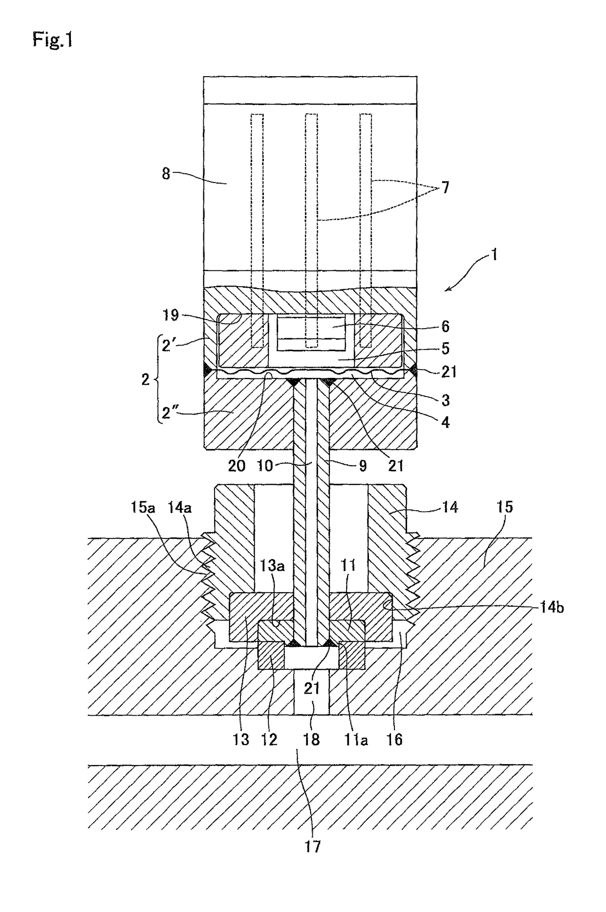
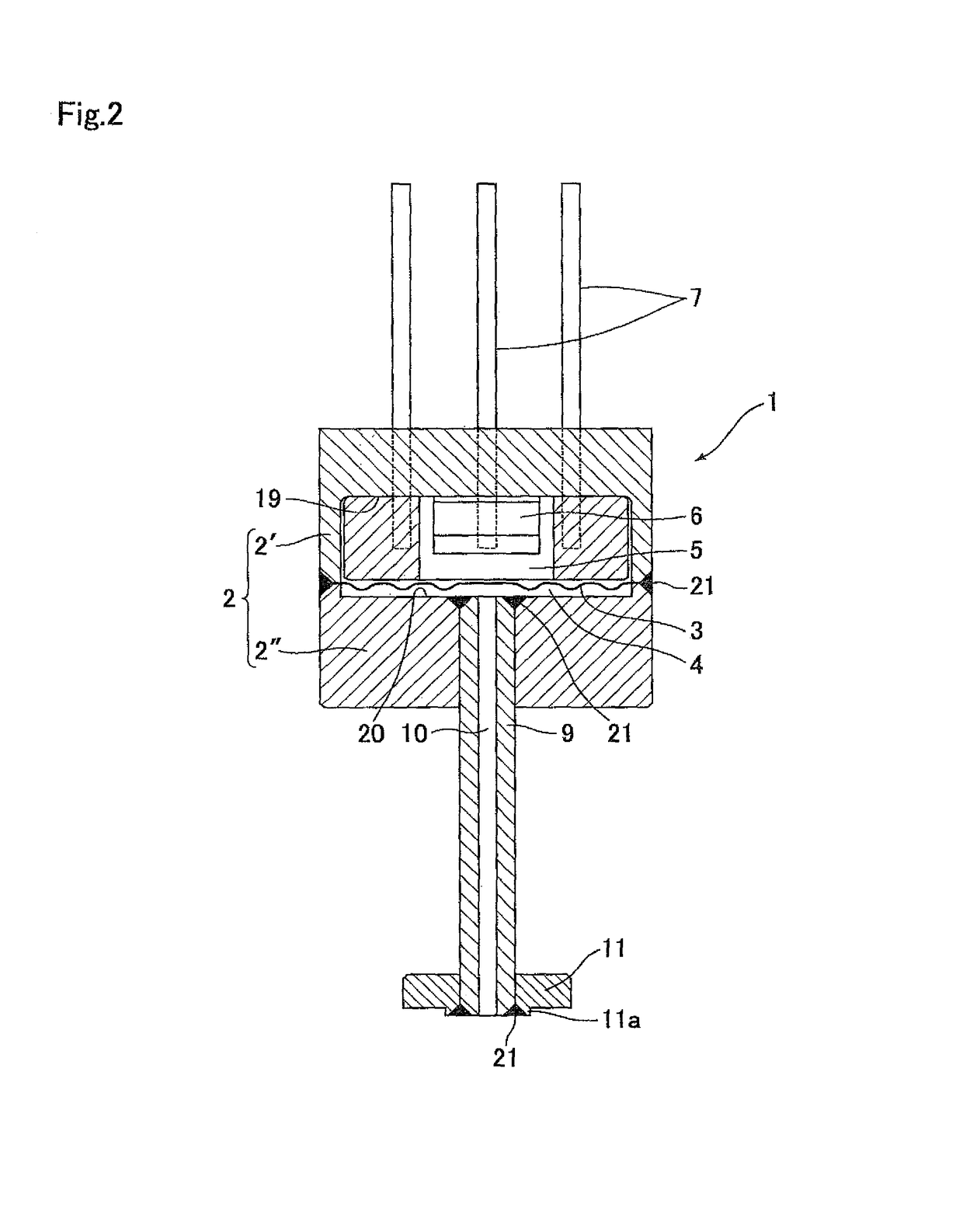
[0065]FIG. 1 shows an embodiment of the present invention according to the structure for attaching the pressure detector. In FIG. 1, reference numeral 1 represents a diaphragm type pressure detector, 2 represents a casing composed of a sensor base 2′ and a tube base 2″, 3 represents a partition diaphragm, 4 represents a pressure receiving chamber in the casing 2, 5 represents a pressure chamber in the casing 2, 6 represents a pressure detecting element provided with a pressure detecting diaphragm (not illustrated), 7 represents a lead pin, 8 represents a cover, 9 represents a pipe, 10 represents a pressure introduction hole, 11 represents a gasket presser, 12 represents a gasket, 13 represents a split ring, 14 represents a bonnet, 15 represents an attachment tool main body attached to pipelines or mechanical devices, 16 represents an insertion hole of a pressure detector 1 formed on the att...


PUM

PropertyMeasurementUnit
thicknessaaaaaaaaaa
thicknessaaaaaaaaaa
thicknessaaaaaaaaaa

Abstract

An attachment structure for a pressure detector that is such that the pressure detector is attached in an airtight manner within an insertion hole of an attachment tool main body attached to a mechanical device or pipelines, with a pipe, a gasket presser, a gasket, a split ring, and a bonnet. The configuration is such that the gasket presser and the split ring are inserted into the insertion hole of the attachment tool main body, the bonnet is inserted into the insertion hole, the bonnet is fastened to the attachment tool main body side, the gasket presser and the gasket are pressed by the split ring, and sealing portions are formed between the bottom surface of the insertion hole and one end surface of the gasket and between the tip end surface of the gasket restraint and the other end surface of the gasket.

Description

FIELD OF THE INVENTION[0001]The present invention relates to an improvement of the structure for attaching a diaphragm type pressure detector utilizing a pressure detecting element (pressure sensitive element or strain gauge), which are mainly used for gas supply systems in semiconductor manufacturing facilities.BACKGROUND OF THE INVENTION[0002]Heretofore, diaphragm type pressure detectors utilizing pressure detecting elements (for example, pressure sensitive elements) have been widely used for detecting hydrostatic pressures in conduit lines (for example, refer to patent document 1).[0003]FIGS. 9 to 11 show examples of a conventional diaphragm type pressure detector 30. The pressure detector 30 is composed of a sensor base 31, a pressure detecting element 32, a diaphragm base 34 including a diaphragm 33, a pressure transmission medium 35 (silicone oil), a sealing ball 36, a lead pin 37, and other components. When a hydrostatic pressure 38 applied onto the pressure detecting element...

Claims


Application Information

Patent Timeline
Patent Type & Authority Patents(United States)
IPC IPC(8): F16K41/00F16L21/03F16L21/04G01L19/00G01L19/14G01L9/00F16L41/00
CPCF16L21/03F16L21/04G01L9/0051G01L19/145G01L19/147G01L19/003F16L41/008
Inventor DOHI, RYOUSUKENISHINO, KOUJIIKEDA, NOBUKAZUFUKASAWA, MASAKIISHIGURO, KATSUMI
Owner COPAL ELECTRON CO LTD
Why Eureka
Try Eureka