Toner, developing apparatus, and image-forming apparatus

a developing apparatus and toner technology, applied in the field of toner, can solve the problems of affecting the development efficiency of the developing apparatus, etc., and achieves excellent low-temperature fixability, excellent developing performance, and suppression of fogging

Active Publication Date: 2018-07-03
CANON KK
View PDF75 Cites 24 Cited by
  • Summary
  • Abstract
  • Description
  • Claims
  • Application Information

AI Technical Summary

Benefits of technology

[0011]Thus, as indicated in the preceding, there was still room for investigations and room for improvement with regard to a toner that—even after heat cycling and even when subjected to stress during a durability challenge as in a cleanerless system—would exhibit an excellent developing performance and would be able to support fixing at low pressures and small amounts of heat.
[0012]An object of the present invention is to provide a toner that—after heat cycling and / or when exposed to a durability challenge—exhibits a suppression of fogging and has an excellent low-temperature fixability. A further object of the present invention is to provide a developing apparatus and an image-forming apparatus that have this toner.
[0016]The present invention can thus provide a toner that—after heat cycling and / or when exposed to a durability challenge—exhibits a suppression of fogging and has an excellent low-temperature fixability. The present invention can also provide a developing apparatus and an image-forming apparatus that have this toner.

Problems solved by technology

However, characteristic problems are also present with cleanerless systems.
Due to this, stress is applied between members not only in the developing step, but also in the charging step and the recovery step, and toner deterioration, i.e., the burying of external additives and toner cracking, can then occur.

Method used


Image

  • Toner, developing apparatus, and image-forming apparatus
  • Toner, developing apparatus, and image-forming apparatus
  • Toner, developing apparatus, and image-forming apparatus

Examples


example 1

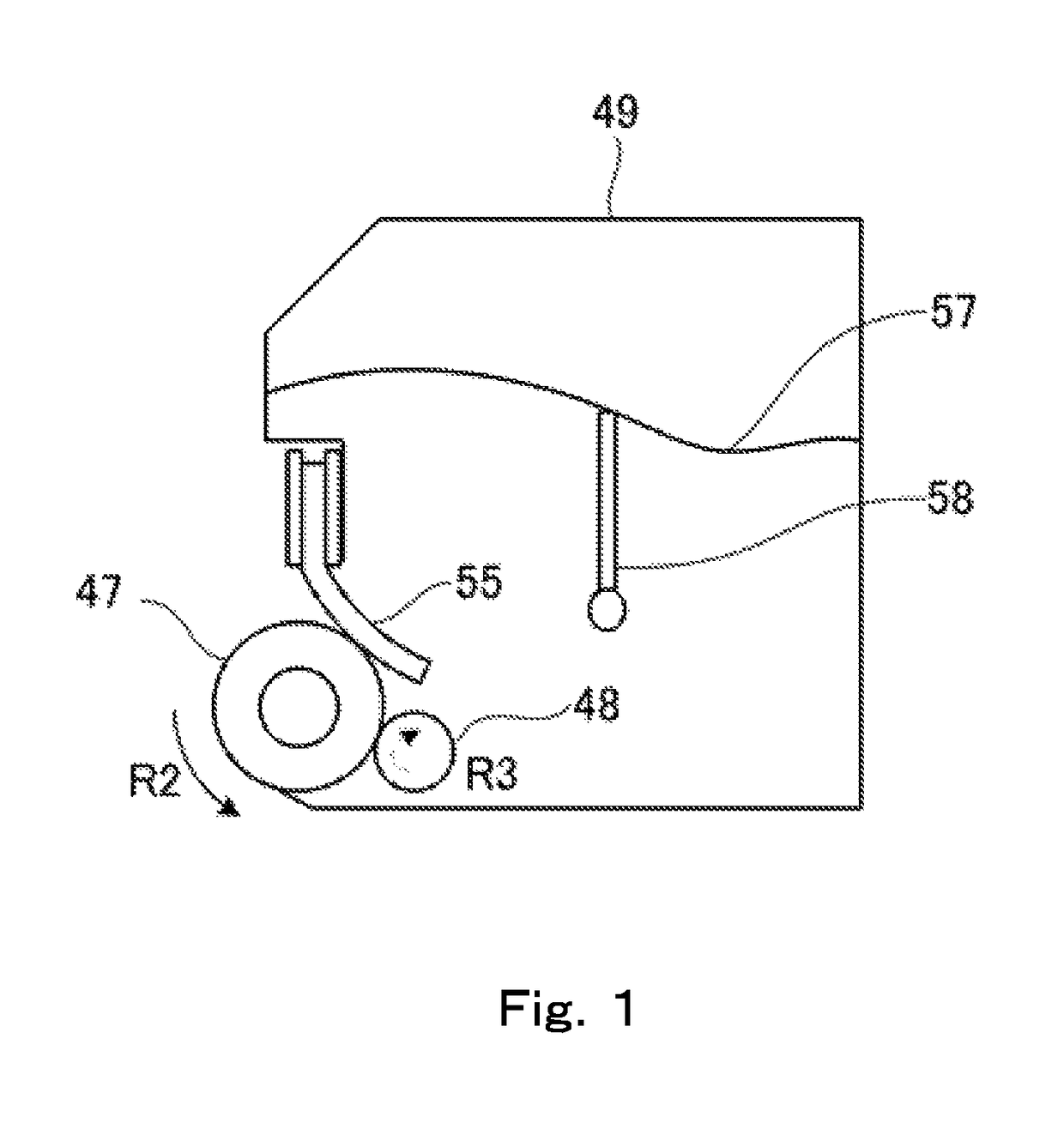
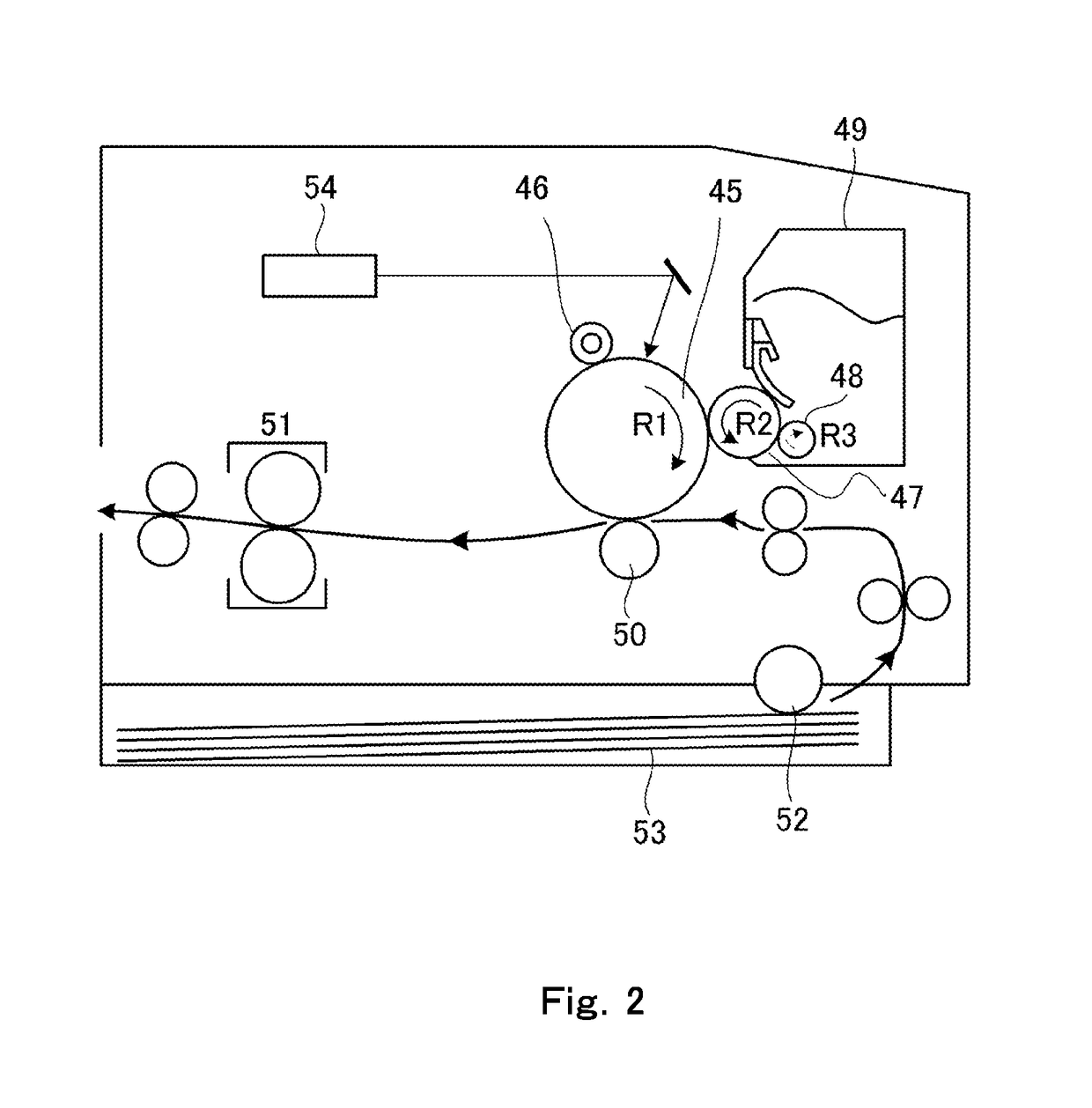
[0405]A modified LBP7700C printer from Canon, Inc. was used in the image output evaluations. The modifications included the following: the toner-carrying member was changed to the toner-carrying member 1 described above; the toner feed member in the developing apparatus was made to undergo counter-rotation versus the toner-carrying member, as shown in FIG. 1; and the application of voltage to the toner feed member was turned off. In addition, the contact pressure was adjusted to bring the width of the contact region between the toner-carrying member and the electrostatic latent image-bearing member to 1.1 mm.

[0406]In addition, the voltage applied to the toner-carrying member was modified from the finished product condition to enable it to be 200 V higher than the finished product condition. (For example, if the voltage applied to the toner-carrying member in the finished product is −600 V, the condition of 200 V higher than the finished product condition is −400 V.)

[0407]In other mo...

examples 2 to 32

[0423]Image output evaluations were performed as in Example 1, but changing the toners as indicated in Table 6. According to the results, excellent images could be obtained that presented few image defects. The results of the evaluations are given in Table 6.


PUM


Abstract

A toner comprising a toner particle containing a binder resin, a colorant, an amorphous polyester, and a crystalline polyester, wherein the binder resin contains a vinyl resin; the amorphous polyester has a monomer unit derived from a linear aliphatic dicarboxylic acid having 6 to 12 carbons, and a monomer unit derived from a dialcohol; the content of the monomer unit derived from a linear aliphatic dicarboxylic acid having 6 to 12 carbons is 10 to 50 mol % with reference to the total monomer units derived from a carboxylic acid in the amorphous polyester; and in a cross section of the toner particle, the vinyl resin constitutes a matrix and the amorphous polyester constitutes domains, and the crystalline polyester is present in the interior of the domains.

Description

BACKGROUND OF THE INVENTIONField of the Invention[0001]The present invention relates to a toner used for toner jets and in image-forming methods for the visualization of electrophotographic and electrostatic images. The present invention further relates to a developing apparatus and an image-forming apparatus.Description of the Related Art[0002]In the past, a printer was frequently used connected to a network and a large number of individuals would then print to this printer. However, in recent years, there has also been strong demand for locating the PC and printer at an individual's desk in order to carry out local printing. Due to this, the space taken up by the printer must be reduced and there is thus strong demand for reducing printer size.[0003]In addition, focusing on the environment in which printers are used, they are being used over a broad range from low-temperature, low-humidity environments to high-temperature, high-humidity environments. Moreover, in regions where lar...

Claims


Application Information

Patent Timeline
Patent Type & Authority Patents(United States)
IPC IPC(8): G03G9/087G03G9/09G03G9/083G03G9/08G03G15/02
CPCG03G9/0825G03G9/081G03G9/0833G03G9/08724G03G9/08755G03G9/0904G03G9/08708G03G15/0216G03G9/0804G03G9/08711G03G9/08795G03G9/08797
Inventor MATSUI, TAKASHINAGASHIMA, YUUJIROUTANAKA, KEISUKETSUDA, SHOHEIOKAMOTO, NAOKI
Owner CANON KK
Why Eureka
Try Eureka