
Power conversion device and method for diagnosing abnormality in voltage sensor characteristics

a technology of voltage sensor and characteristic, which is applied in the direction of electric variable regulation, process and machine control, instruments, etc., can solve the problems of poor diagnosis accuracy, inability to diagnose the voltage detection function directly, and inability to directly diagnose the voltage detection function. , to achieve the effect of high accuracy, simple configuration and convenient and inexpensive us

Active Publication Date: 2018-07-03
MITSUBISHI ELECTRIC CORP
View PDF12 Cites 5 Cited by
  • Summary
  • Abstract
  • Description
  • Claims
  • Application Information

AI Technical Summary

Benefits of technology

[0009]The present invention has been devised in view of the conventional problems described above, an object thereof being to achieve a power conversion device and a method for detecting an abnormality in voltage sensor characteristics, with which the presence / absence of an abnormality in a voltage detection function of a voltage sensor can be diagnosed in a broad voltage range, easily and inexpensively by a simple configuration, and it can be diagnosed with high accuracy whether or not unexpected variation has occurred in the detection characteristics of the voltage sensor.
[0012]According to the present invention, a configuration is achieved in which it is possible to make a diagnosis of the presence / absence of an abnormality in the detection characteristics of a voltage sensor, from the state of transition in detection results from each voltage sensor as monitored during a discharge operation. Therefore, it is possible to achieve a power conversion device and a method for detecting an abnormality in voltage sensor characteristics, whereby the presence / absence of an abnormality in a voltage detection function of a voltage sensor can be diagnosed in a broad voltage range, easily and inexpensively by a simple configuration, and it can be diagnosed with high accuracy whether or not unexpected variation has occurred in the detection characteristics of the voltage sensors.

Problems solved by technology

The prior art involves the following problems, however.
This method, however, requires means for generating an abnormal voltage from an external source and, moreover, does not diagnose the voltage detection function directly.
Therefore, Japanese Patent Application Publication No. 2010-008153 has a problem in that the diagnosis accuracy is poor.
However, this method does not diagnose the voltage detection function by direct calculation.
Therefore, Japanese Patent Application Publication No. 2007-282299 also has a problem in that the diagnosis accuracy is poor.

Method used


Image

  • Power conversion device and method for diagnosing abnormality in voltage sensor characteristics
  • Power conversion device and method for diagnosing abnormality in voltage sensor characteristics
  • Power conversion device and method for diagnosing abnormality in voltage sensor characteristics

Examples


first embodiment

[0017

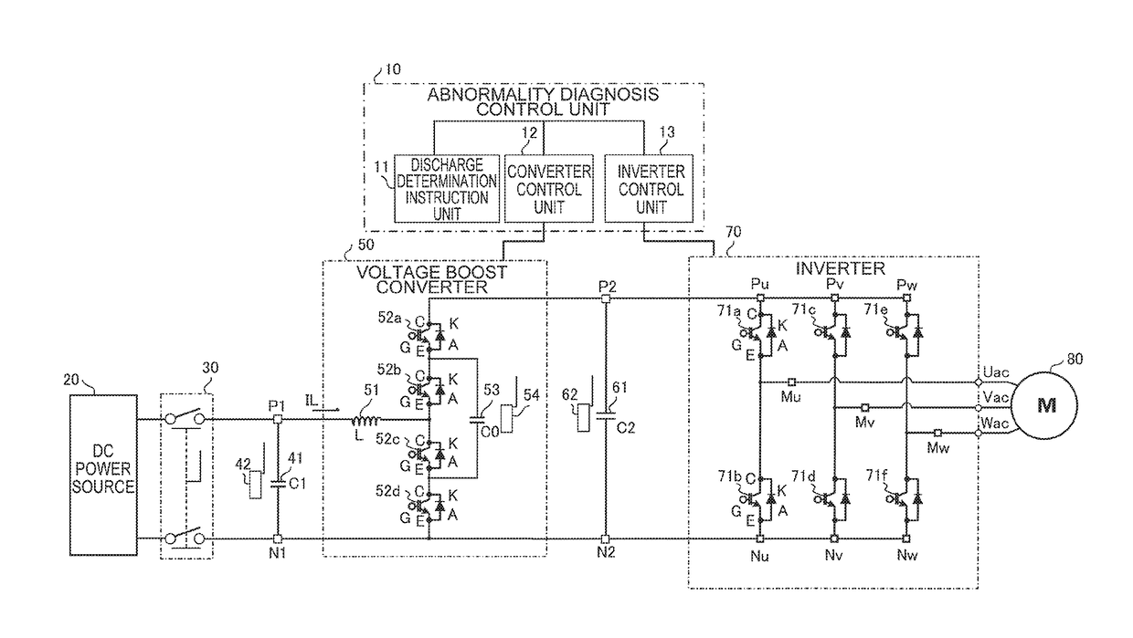
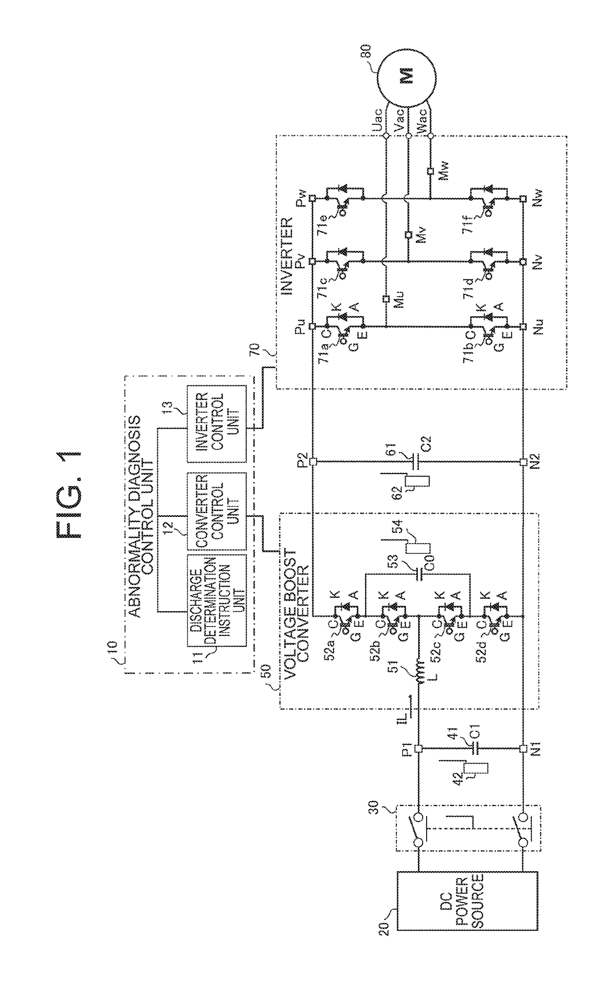
[0018]FIG. 1 is a schematic drawing showing a power conversion device relating to the first embodiment of the present invention. The power conversion device illustrated in FIG. 1 comprises an abnormality diagnosis control unit 10 (an abnormality diagnosis controller 10), a DC power source 20, a relay 30, a primary smoothing capacitor 41, a primary-side voltage sensor 42, a voltage boost converter 50, a secondary smoothing capacitor 61, a secondary-side voltage sensor 62, an inverter 70 and an electric motor 80.

[0019]The DC power source 20 is chargeable / dischargeable, and exchanges power with the electric motor 80 via the voltage boost converter 50 and the inverter 70.

[0020]The voltage boost converter 50 is connected between the DC power source 20 and the inverter 70. The voltage boost converter 50 is configured from a reactor 51, semiconductor switch elements 52a to 52d, and an energy transfer capacitor 53.

[0021]In the description given below, the energy transfer capacitor 53 i...

second embodiment

[0063

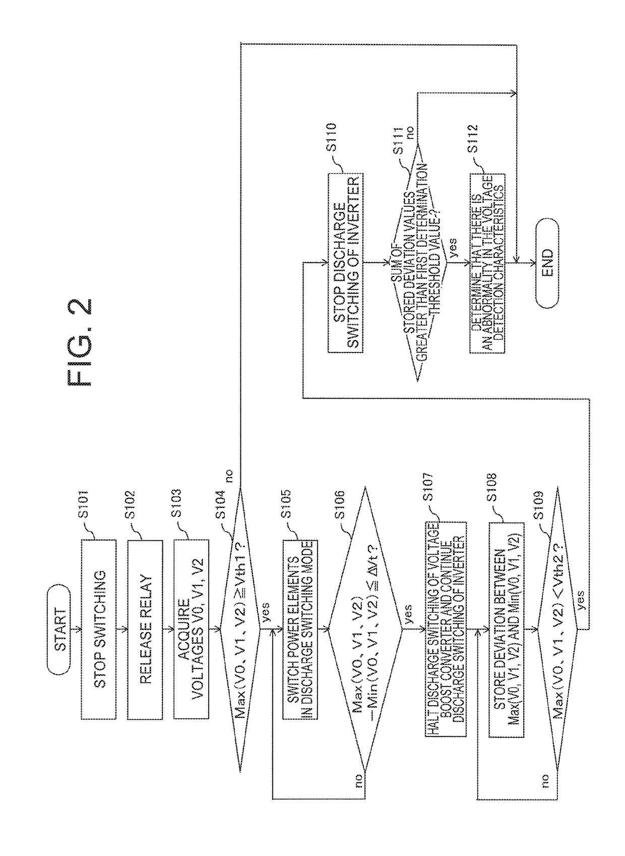
[0064]In the first embodiment above, an abnormality in the voltage detection characteristics is diagnosed by comparing and determining whether or not the sum of stored deviation values exceeds a first determination threshold value. On the other hand, in the second embodiment, an abnormality in the voltage detection characteristics is diagnosed in a simpler fashion, without determining the sum of the stored deviation values.

[0065]The configuration of the power conversion device according to the second embodiment is the same as the configuration in FIG. 1 relating to the first embodiment above and description thereof is omitted here. The process for diagnosing the voltage detection characteristics in the second embodiment is described with reference to a flowchart.

[0066]FIG. 3 is a flowchart illustrating a processing sequence relating to the method for diagnosing an abnormality in a voltage detection function according to the second embodiment of the present invention. In compari...


PUM


Abstract

A power conversion device provided with a DC power source, a voltage boost converter, an inverter, a primary smoothing capacitor, a secondary smoothing capacitor, an intermediate capacitor provided in the voltage boost converter and three voltage sensors which measure the voltages of the capacitors, further including an abnormality diagnosis controller which makes a diagnosis of the presence / absence of an abnormality in the detection characteristics of the voltage sensors, on the basis of the state of transition of the detection results of the voltage sensors which are monitored during a discharge operation by the respective capacitors.

Description

BACKGROUND OF THE INVENTION[0001]1. Field of the Invention[0002]The present invention relates to a power conversion device provided with a voltage boost converter and an inverter, and more particularly, to a power conversion device which diagnoses the presence or absence of a failure in the voltage detection function of the voltage sensor, and a method for diagnosing an abnormality in the voltage sensor characteristics, on the basis of monitoring results of the voltage detection values of a plurality of voltage sensors which are used for voltage conversion control.[0003]2. Description of the Related Art[0004]A power conversion device having a DC / DC voltage conversion function is generally provided with a voltage sensor which monitors a plurality of voltages including an input voltage and an output voltage, and voltage conversion control is carried out by using the signal detected by these voltage sensors.[0005]If there is a failure in the voltage detection function of the voltage se...

Claims


Application Information

Patent Timeline
Patent Type & Authority Patents(United States)
IPC IPC(8): B60L1/00G01R19/00H02M3/158H02M7/537H02P27/00G01R19/165
CPCH02M3/158G01R19/003H02P27/00H02M7/537G01R19/165G01R31/2829H02M1/32H02M7/5387H02P27/06H02P29/0241H02M1/007
Inventor KOBAYASHI, MASARUIDENOUE, SHINSUKEISHII, SATOSHIOTSUKA, KAZUHIKOABE, JUNICHI
Owner MITSUBISHI ELECTRIC CORP
Learn More