Sampling apparatus

a sampling apparatus and equipment technology, applied in the field of sampling equipment, can solve the problems of poor sampling accuracy, complex structure of the apparatus, and inability to ascertain from rock material, so as to improve the sampling accuracy and simplify the sampling process

Active Publication Date: 2018-07-10
ERIMEK
View PDF9 Cites 0 Cited by
  • Summary
  • Abstract
  • Description
  • Claims
  • Application Information

AI Technical Summary

Benefits of technology

[0006]The aim of the present invention is thus to eliminate, inter alia, the aforementioned drawbacks of prior-art solutions, and to achieve an apparatus with which a more truly representative sample than before with respect to sampling of the excavated ore can be produced. Further, the aim of this invention is to bring about the following advantages: to achieve a better level in sampling accuracy, to achieve savings in the labor costs in sampling, and to achieve a better work safety level and work hygiene level in sampling.
[0009]Only a part of the whole flow of rock material plus air coming from the hole flies into the sampling aperture on the frontal surface area. Selecting the size of the aperture advantageously achieves the benefit that less post-processing of a sample by splitting, or with another such method, is needed or is not needed at all. The representativeness of a sample is better than that of methods known in the art, because the sample contains also particles normally escaping as airborne dust.
[0013]The suction nozzle is shaped in such a way that it protects the rest of the structure of the sampler from wear by rock material flying out of the hole by guiding the air coming out of the borehole to pass by the side of the support structures of the suction nozzle.

Problems solved by technology

Drilling field conditions are typically dusty and the nature of the flying dust detaching from the piles can be detrimental to the health of the employee collecting the samples.
A weakness with pile samples is that it is no longer possible to ascertain from the rock material taken from a pile information about the depth of adjoining rock deposits or ore deposits from the drilling level.
Particular drawbacks in sampling apparatuses according to prior art are poor sampling accuracy and the complex structure of the apparatus.

Method used


Image

  • Sampling apparatus
  • Sampling apparatus
  • Sampling apparatus

Examples


Embodiment Construction

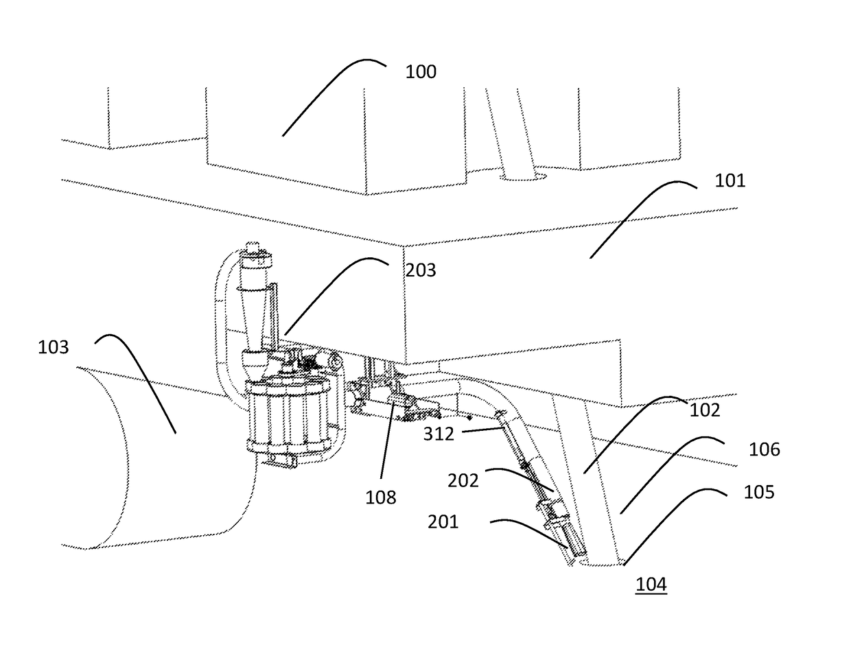
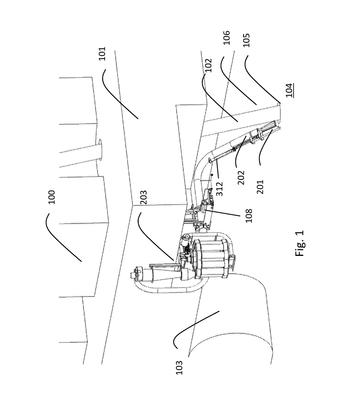
[0022]FIG. 1 presents a simplified view of a mobile crawler-tracked drill rig 100 used in open-cast mines, said rig including a chassis 101, and a drill fitted into the rig, said drill including an extendable boring pipe 102 and a drill bit (not presented) on the end of it. The drill rig according to FIG. 1 includes motor-driven crawler tracks 103, by the aid of which the drill rig can be moved in the mining area. In addition, the drill rig 100 includes a control unit 108 for controlling it.

[0023]Holes 105 are bored in the ground 104 with the drill, from which holes rock material 106 discharges out of the borehole onto the surface of the ground. The apparatus according to FIG. 1 is used in drilling deep boreholes, in which case compressed air, or a compressed air-water mix, is blown via the stem 102 of the drill bit to transport the rock material that is detached by the drill bit out of the hole.

[0024]For sampling the drill rig includes a sampling apparatus, according to the inventi...


PUM


Abstract

A sampling apparatus for collecting geological samples from the subsurface is fixable to a drill, such as to a mining drill rig. The drill apparatus includes a chassis, and a drill comprising a boring pipe and a drill bit. The sampling apparatus is fixable to the chassis of the drill apparatus and includes a sampling pipe arrangement to be fitted to the end of it, as well as a collecting apparatus to be connected to the sampling pipe apparatus, in which the collecting apparatus samples can be collected. The nozzle is a suction nozzle, in which suction is arranged. The sampling pipe arrangement comprises an attitude adjustment apparatus, with which the nozzle can be arranged into the proximity of the boring pipe in such a way that the nozzle is near the borehole and the mouth of it is directed towards the borehole such that it is able to take samples directly from the mantle rock flying out from the borehole.

Description

CROSS REFERENCE TO RELATED APPLICATION[0001]This application is a Continuation of PCT International Patent Application No. PCT / FI2013 / 050872 filed on Sep. 10, 2013, which claims the benefit of Finnish Patent Application No. 20125965 filed Sep. 19, 2012, the entire disclosure of each of which is incorporated herein by reference in its entirety.FIELD OF THE INVENTION[0002]The object of the invention is an apparatus intended for collecting geological samples, which apparatus is suited e.g. for underground drilling use.BACKGROUND OF THE INVENTION[0003]The excavating of ore or other minerals is performed typically at mines by drilling and by loading a number of pluralities of deep holes in an advantageous grouping in terms of the blasting technique. Compressed air, or a compressed air-water mix, blown via the boring pipe is used in drilling the deep holes to transport the rock material that is detached by the drill bit out of the hole. Due to the action of the compressed air, rock materi...

Claims


Application Information

Patent Timeline
Patent Type & Authority Patents(United States)
IPC IPC(8): E21B49/02E21B21/01E02D1/02
CPCE21B49/02E21B21/01E02D1/02E21B49/005
Inventor LINDFORS, ERIK
Owner ERIMEK
Why Eureka
Try Eureka