Drilling type sidewall coring apparatus

a coring apparatus and sidewall technology, applied in the field of drilling type sidewall coring apparatus, can solve the problems of high risk, low power transmission efficiency of hydraulic pump and hydraulic motor, and large difficulty in downhole power supply, and achieve the effect of high drilling efficiency

Active Publication Date: 2018-07-10
CHINA NAT OFFSHORE OIL CORP +1
View PDF13 Cites 1 Cited by
  • Summary
  • Abstract
  • Description
  • Claims
  • Application Information

AI Technical Summary

Benefits of technology

[0009]The above sidewall coring apparatus uses the soft shaft and the speed reducer to transmit the power the bit needs when drilling, the efficiency of which is higher relative to the hydraulic pump and hydraulic motor and will not vary with the temperature. The success rate of coring is greatly increased without the need of frequently replacing the hydraulic oil. The workload of site maintenance is largely reduced and at the same time the risk of site operation is effectively reduced.
[0010]The other object of the embodiments of the present invention is to provide a sidewall coring apparatus with a simple and reliable telescopic mechanism of the bit.
[0011]The further object of the embodiments of the present invention is to provide a sidewall coring apparatus which can complete core folding without being limited to the coring depth.
[0021]The above drilling type sidewall coring apparatus is provided with the rack in the main body, the transmission device installed with the bit is mounted on the rack, using the hydraulic oil cylinder to directly drive the rack to perform radial motion in the main body so as to achieve the protruding and retracting of the bit, and the structure can be simply achieved and is reliable, which improves the precision of coring. Preferably, the second hydraulic oil cylinder and the linkage mechanism needed for achieving the rotation and swing of the bit are mounted on the rack, moving with the rack, so as to avoid the case of coring failure when the bit gets stuck.

Problems solved by technology

However, the power transmission efficiency of hydraulic pump and hydraulic motor is very low, particularly when the temperature is of great changes, the viscosity of hydraulic oil varies a lot, even the efficiency is lower.
In order to guarantee the bit 1002 to have sufficient power to complete coring operation, the power of the electric motor must be very large, while the request for large power of the electric motor leads to the great difficulty of downhole power supply and higher risk.
If the bit 1002 gets stuck to not reach the appointed depth during the coring process, the core folding and coring cannot be achieved.

Method used


Image

  • Drilling type sidewall coring apparatus
  • Drilling type sidewall coring apparatus
  • Drilling type sidewall coring apparatus

Examples


Embodiment Construction

[0033]The embodiments of the present invention will be described in detail below in conjunction with accompanying drawings. It should be illustrated that without a conflict, the embodiments in the present application and the features in the embodiments can be combined with each other randomly.

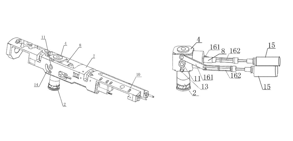
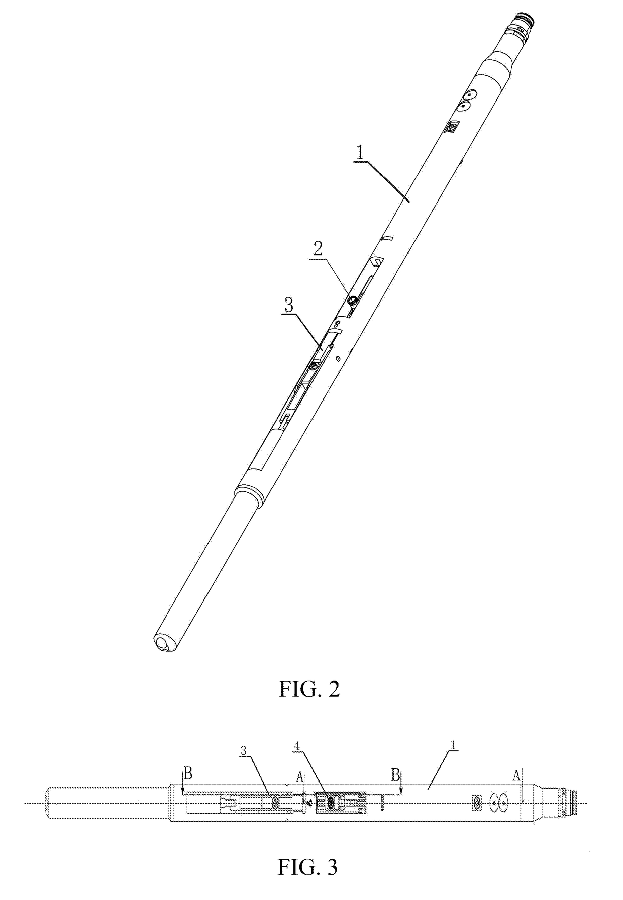
[0034]FIGS. 2 and 3 respectively show the perspective view and the top view of the drilling type sidewall coring apparatus according to the embodiments of the present invention. The sidewall coring apparatus according to the embodiments of the present invention comprises a main body 1, from the surface of which a right angle speed reducer 4, a backup arm 3 and the like can be observed.

[0035]FIG. 4 is a sectional view of A-A shown in FIG. 3 and FIG. 5 is a sectional view of B-B shown in FIG. 3. A power mechanism for achieving the drilling of the bit shown in FIG. 4 comprises a bit 2, a right angle speed reducer 4, a soft shaft 5 and an electric motor 6, one end of the soft shaft 5 being connecte...


PUM


Abstract

A drilling type sidewall coring apparatus, comprising: a main body, a transmission device, a bit mounted on the transmission device, a rack accommodated in the main body, and a plurality of first hydraulic oil cylinders, the transmission device mounted on the rack in a rotatable manner, the first hydraulic oil cylinders mounted on the main body, pistons of the first hydraulic oil cylinders connected with the rack, the telescopic motion of the pistons of the first hydraulic oil cylinders driving the rack to perform radial motion in the main body so as to make the bit protrude or retract from the main body. The electric motor is mounted in the main body and connected with the right angel speed reducer by the soft shaft. The electric motor transmits power by the soft shaft and the right angle speed reducer to drive the bit to rotate, the transmission efficiency is higher.

Description

TECHNICAL FIELD[0001]The embodiments of the present invention relate to the field of petroleum exploration, in particular to a drilling type sidewall coring apparatus.BACKGROUND OF THE RELATED ART[0002]The drilling type sidewall coring apparatus is a petroleum exploration apparatus. US patent US 2013 / 0068531A1 discloses a drilling type sidewall coring apparatus. As shown in FIG. 1, a coring apparatus 100 is lowered into a well, a bit 1002 drills into the formation, perpendicular to the sidewall, for coring and core folding operations, and the bit 1002 completes the core-pushing operation after retracting into a main body 1001. The operation process of the coring apparatus 100 is: a ground panel controls an electric motor of the downhole coring apparatus 100, the electric motor drives a hydraulic pump to produce high pressure to drive a backup arm 1003 to deploy such that the coring apparatus is fixed in the depth of coring and is pressed firmly against the sidewall; meanwhile, the h...

Claims


Application Information

Patent Timeline
Patent Type & Authority Patents(United States)
IPC IPC(8): E21B49/06E21B4/04E21B4/00E21B4/16E21B4/18E21B23/01
CPCE21B49/06E21B4/006E21B4/16E21B4/18E21B4/04E21B23/01
Inventor FENG, YONGRENTIAN, ZHIBINLU, TAOLIU, LIPINGHAO, GUIQINGZHANG, WENQUANCHU, XIAODONGWEI, ZANQINGLIU, TIEMINHAN, FEN
Owner CHINA NAT OFFSHORE OIL CORP
Why Eureka
Try Eureka