
Flash memory apparatus and storage management method for flash memory

a flash memory and storage management technology, applied in the field of flash memory apparatus, can solve the problems of poor user experience, inability to accept users, and inevitably lower utilization rate of flash memory space, so as to reduce the number of necessary parity check codes and reduce error rates

Active Publication Date: 2018-07-10
SILICON MOTION INC (TW)
View PDF44 Cites 76 Cited by
  • Summary
  • Abstract
  • Description
  • Claims
  • Application Information

AI Technical Summary

Benefits of technology

This approach reduces the number of necessary parity check codes, enhances error correction capabilities, and increases the utilization rate of flash memory space by efficiently using memory locations for both data and parity check codes.

Problems solved by technology

However, the utilization rate of a flash memory space inevitably becomes lower.
This poor user experience is usually cannot be accepted for users.

Method used


Image

  • Flash memory apparatus and storage management method for flash memory
  • Flash memory apparatus and storage management method for flash memory
  • Flash memory apparatus and storage management method for flash memory

Examples


first embodiment

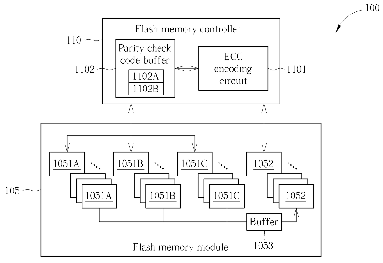
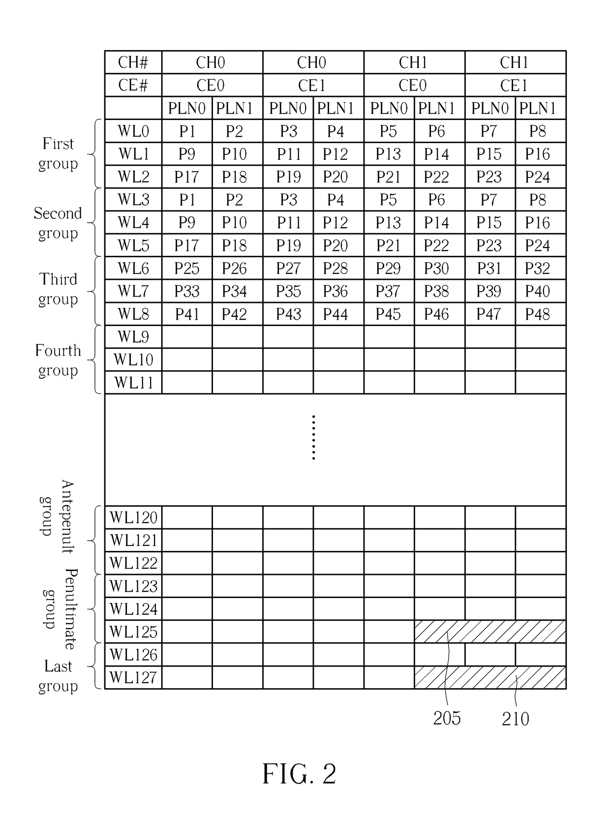
[0041]Please refer to FIG. 2, which is a diagram illustrating one SLC programming executed by the flash memory controller 110 of FIG. 1 to program a particular group of data into an SLC block of flash memory module 105 according to the invention. The ECC encoding circuit 1101 of flash memory controller 110 is arranged to perform RAID-like RS (Reed Solomon) encoding operation upon data to generate corresponding parity check codes, and the parity check code buffer 1102 is used for temporarily storing the generated parity check codes.

[0042]The flash memory module 105 includes two channels and two flash memory chips in which two sets of blocks of each chip include two different planes. To improve the efficiency of data programming, the flash memory controller 110 is arranged for respectively programming / writing data via the two channels into two different blocks of the two flash memory chips within flash memory module 105. As shown in FIG. 2, in this embodiment, one SLC block for exampl...

second embodiment

[0059]Please refer to FIG. 5, which is a diagram illustrating one SLC programming executed by the flash memory controller 110 of FIG. 1 to program a particular group of data into an SLC block of flash memory module 105 according to the invention. The ECC encoding circuit 1101 of flash memory controller 110 is arranged to perform. RAID-like XOR (exclusive-OR) encoding operation upon data to generate corresponding parity check codes, and the parity check code buffer 1102 is used for temporarily storing the generated parity check codes. In addition, the XOR operation of ECC encoding circuit 1101 includes three different encoding engines to respectively perform XOR operations upon different word line data of SLC block(s). The description is detailed in the following paragraphs.

[0060]The flash memory module 105 includes two channels and two flash memory chips. To improve the efficiency of data programming, the flash memory controller 110 is arranged for respectively programming / writing d...


PUM


Abstract

A method used for a flash memory module having a plurality of storage blocks each can be used as a first block or a second block includes: classifying data into a plurality of groups of data; respectively executing error code encoding to generate a first corresponding parity check code to store the groups of data and the first corresponding parity check code into the flash memory module as first blocks; reading out the groups of data from the first blocks; executing error correction and de-randomize operation upon read out data to generate de-randomized data; executing randomize operation upon the de-randomized data according to a set of seeds to generate randomized data; performing error code encoding upon the randomized data to generate a second corresponding parity check code; and storing the randomized data and the second corresponding parity check code into the flash memory module as the second block.

Description

CROSS REFERENCE TO RELATED APPLICATIONS[0001]This application is a continuation in part application and claims the benefit of U.S. application Ser. No. 15 / 497,185, filed on Apr. 25, 2017, which claims the benefits of U.S. provisional application Ser. No. 62 / 328,025 filed on Apr. 27, 2016, which is entirely incorporated herein by reference.BACKGROUND OF THE INVENTION1. Field of the Invention[0002]The invention relates to a flash memory apparatus, and more particularly to a flash memory apparatus and a corresponding storage management method for performing RAID-like (Redundant Array of Independent Disks-like) error correction code (ECC) encoding operation.2. Description of the Prior Art[0003]Generally speaking, when performing data programming to program data into a single-level-cell (SLC) block or a multiple-level-cell (MLC) block, a conventional flash memory controller is usually arranged to program corresponding parity check codes of other data pages of a word line of a data block ...

Claims


Application Information

Patent Timeline
Patent Type & Authority Patents(United States)
IPC IPC(8): G11C16/04G11C16/10G11C16/26G06F11/10G11C29/52G11C11/56
CPCG06F11/1068G11C11/5621G11C29/52G11C16/26G11C16/10G11C11/5628G11C11/5642G11C16/0483G11C2211/5641G06F11/1072G06F11/1076
Inventor YANG, TSUNG-CHIEHHSU, HONG-JUNGDU, JIAN-DONG
Owner SILICON MOTION INC (TW)
Learn More