
Insulated wire and method of producing the same

a technology of insulated wire and insulating conductor, which is applied in the direction of insulated conductors/cables, cables, cables, etc., can solve the problems of high surge voltage, high steep voltage rise, and output pulse due to high-speed switching devices, and achieve excellent abrasion resistance and thermal aging resistance, suppress the effect of lowering the rupture strength of the conductor

Active Publication Date: 2018-07-10
ESSEX FURUKAWA MAGNET WIRE LLC
View PDF31 Cites 1 Cited by
  • Summary
  • Abstract
  • Description
  • Claims
  • Application Information

AI Technical Summary

Benefits of technology

[0043]An aluminum conductor insulated wire of the present invention has features of being excellent in adhesion force between a conductor and an adhesion layer, and between the adhesion layer and an insulation layer, and excellent in both of abrasion resistance and thermal aging resistance, and further excellent in suppressing lowering in rupture strength of the conductor, and high in partial discharge inception voltage.

Problems solved by technology

In particular, an output pulse occurred due to a high-speed switching device, such as an IGBT (insulated gate bipolar transistor), is high in steep voltage rise.
Accordingly, even if a connection cable is short, the surge voltage is high, and voltage decay due to the connection cable is also low.
That is, inverter surge deterioration of an enameled layer is a phenomenon in which partial discharge occurs in the insulated wire due to the surge voltage with a high peak value, which is occurred at the inverter, and the coating of the insulated wire causes partial discharge deterioration as a result of the partial discharge, resulting in that the inverter surge deterioration of an enameled layer of the coating of the insulated wire is high-frequency partial discharge deterioration.
However, in the former method, if other characteristics (heat resistance, solvent resistance, flexibility, and the like) required for the enameled layer are taken into consideration, it is difficult to select the resin having a particularly low in relative permittivity.
As a result, there has existed a problem in which workability, such as flexibility, is significantly lowered.
Moreover, if the thickness to be applied in one-time baking is increased in order to reduce the number of times passing through the baking furnace, there has existed a disadvantage in which a solvent in varnish is not wholly evaporated and remains as gas bubbles in the enameled layer.
Owing to these two phenomena, there has existed a problem in which reliability as the winding wire is reduced, such as lowering in accuracy of a conductor diameter or rupture strength (breaking strength) of the conductor by increasing the number of times of baking, in the case of the aluminum conductor enameled wire.
However, no studies have been made on the adhesion force between the conductor and the enameled layer in the arts proposed in Patent Literatures 1 and 2.
When coil winding on the motor or the transformer is performed in a state in which the adhesion force between the conductor and the enameled layer is low, damage is readily caused on the electrical wire coating in the coil working step, to cause a problem in which the electrical insulation performance is lowered and the reliability of a product is lowered.
However, there are known that it is difficult to uniformly apply an insulation coating on a rectangular conductor, and that it is particularly difficult to control the thickness of the insulation coating in an insulated wire having a small cross-sectional area.

Method used


Image

  • Insulated wire and method of producing the same
  • Insulated wire and method of producing the same
  • Insulated wire and method of producing the same

Examples


example 1

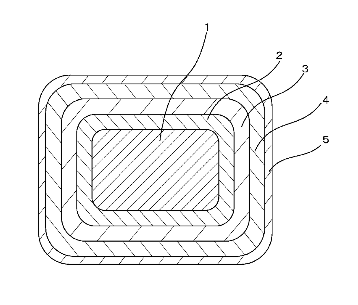
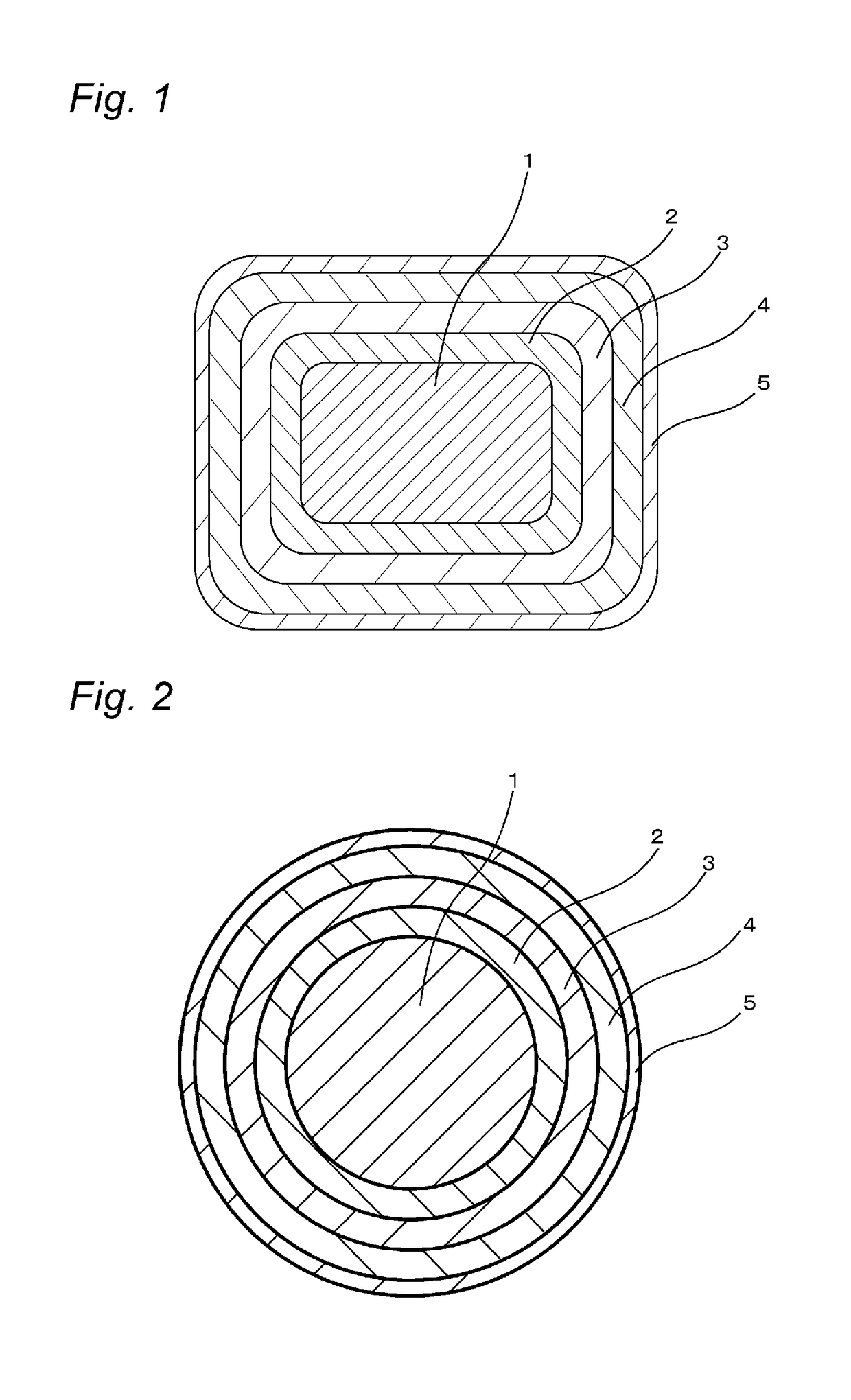
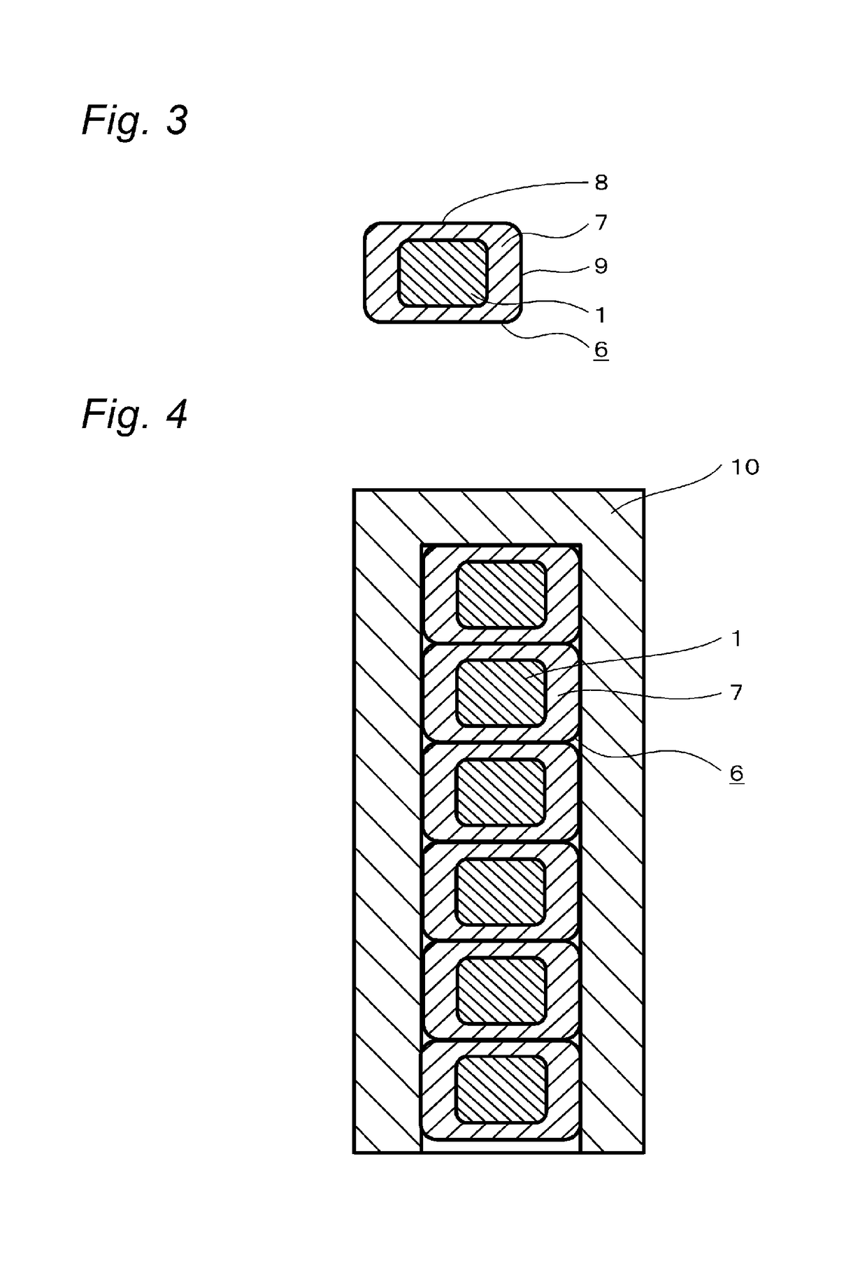
[0160]Each varnish was applied by dip coating and adjusted in an application amount by a die. Specifically, a 5 μm-thick adhesion layer was formed by: applying, on a rectangular conductor (made of 99% purity aluminum) having a rectangular cross section (long side 3.0 mm short side 1.6 mm, r=0.5 mm in which r is a curvature radius of chamfering of four corners), polyimide varnish prepared by adjusting polyimide (PI-1) (trade name U Imide, manufactured by Unitika Ltd.) with N-methyl-2-pyrrolidone (NMP) into 20 mass % in a resin component; and baking the resultant material in a 5-m vertical furnace of natural convection-type under conditions of a furnace temperature of 500° C. and a passing period of time of 30 seconds.

[0161]Then, a 30 μm-thick insulation layer was formed by: applying, onto the adhesion layer, mixed varnish in which polyimide:polyamideimide was 39:61 in a solid content mass ratio, as obtained by mixing, in an equal mass, the above-described polyimide (PI-1) (trade name...

example 2

[0163]An insulated wire having a configuration in Table 1 below was prepared in a manner similar to Example 1.

[0164]Where, for an insulation layer, in place of the polyimide / polyamideimide mixed varnish, polyimide (PI-2) varnish [trade name COMPOCERAN H850D (N,N-dimethylacetamide (DMAc) solution, cured residue 15%, 2 mass % of silica in the cured residue), manufactured by Arakawa Chemical Industries, Ltd.] of a type different from the adhesion layer was used, and for a reinforcement insulation layer, in place of PPS, polyether ether ketone (PEEK) (trade name KetaSpire, manufactured by Solvay Specialty Polymers Japan K.K.) was used.

example 3

[0165]An adhesion layer, an insulation layer, and a reinforcement insulation layer each having a configuration in Table 1 were provided onto the aluminum conductor used in Example 1, in a manner similar to Example 1.

[0166]Where, for an insulation layer, in place of the polyimide / polyamideimide mixed varnish, polyamideimide (PAI-2) varnish [trade name HPC-5000, solid concentration 30%, solvent composition ratio (mass) NMP / xylene=70 / 30, manufactured by Hitachi Chemical Company, Ltd.] was used, and for a reinforcement insulation layer, in place of PPS, polyether ether ketone (PEEK) used in Example 2 was used.

[0167]An insulated wire was prepared by: forming a 5 μm-thick outermost layer, by applying, onto the above-described reinforcement insulation layer, varnish prepared by adjusting polyurethane (trade name TPU F2-NCA, manufactured by Totoku Toryo Co., Ltd.) with cresol into 30 mass % in a resin component; and then baking the resultant material.


PUM

PropertyMeasurementUnit
total thicknessaaaaaaaaaa
glass transition temperatureaaaaaaaaaa

Abstract

An insulated wire which comprises an aluminum conductor, having: an adhesion layer formed by directly baking, on the aluminum conductor, varnish containing a carboxy group; an insulation layer as an outer layer of the adhesion layer; and a reinforcement insulation layer as an outer layer of the insulation layer; and a method of producing the same.

Description

CROSS-REFERENCE TO RELATED APPLICATIONS[0001]This application is a Continuation of PCT International Application No. PCT / JP2015 / 066016 filed on Jun. 3, 2015, which claims priority under 35 U.S.C. § 119 (a) to Japanese Patent Application No. 2014-114954 filed in Japan on Jun. 3, 2014. Each of the above applications is hereby expressly incorporated by reference, in its entirety, into the present application.TECHNICAL FIELD[0002]The present invention relates to an insulated wire and to a method of producing the same.BACKGROUND ART[0003]Inverters have become installed in many types of electrical equipments, as efficient variable-speed control units. Inverters are switched at a frequency of several of kHz to several tens of kHz, to cause a surge voltage at every pulse thereof. Inverter surge is a phenomenon in which reflection occurs at a breakpoint of impedance, for example, at a starting end, a termination end, or the like of a connected wire in the propagation system, and consequently...

Claims


Application Information

Patent Timeline
Patent Type & Authority Patents(United States)
IPC IPC(8): H01B3/30H01B13/14H01B13/00H02K3/30H01B1/02H01B7/00H01B3/42H01B7/02
CPCH01B3/308H01B1/023H01B3/30H01B3/306H01B3/42H02K3/30H01B7/00H01B7/02H01B13/00H01B13/148H01B3/427
Inventor OYA, MAKOTOOBIKA, RYOUSUKETOMIZAWA, KEIICHI
Owner ESSEX FURUKAWA MAGNET WIRE LLC
Learn More