
Fixing device for chairs

a fixing device and chair technology, applied in the direction of chairs, seats, fastening means, etc., can solve the problems of inconvenient use, uneven chairs, and inconvenience for users, and achieve the effect of reducing manufacturing costs and simple structur

Active Publication Date: 2018-07-17
SPEC SEATS TECH
View PDF35 Cites 17 Cited by
  • Summary
  • Abstract
  • Description
  • Claims
  • Application Information

AI Technical Summary

Benefits of technology

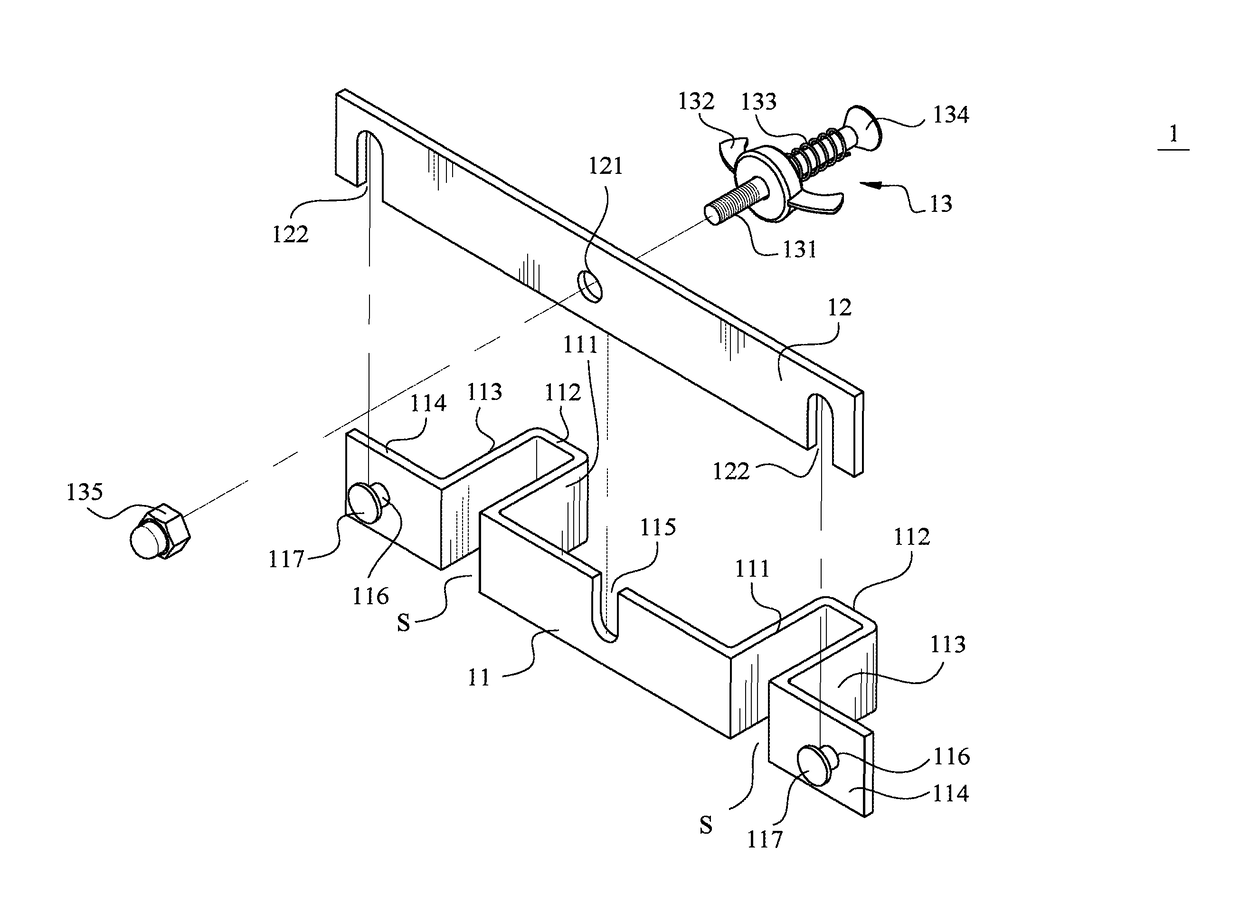
The present invention provides a fixing device for chair that is simple and doesn't require any additional machining, reducing manufacturing expenses. The fixing device includes an encircle element with a notch and a sluice gate with notches to shield and deny access into the encircle element. A locking member prevents untimely disengagement of the sluice gate. The retainer stub on the encircle element has an enlarged head to prevent dislodgement of the sluice gate from the encircle element. A threaded bolt and biasing spring prevent loosening of the first nut on the bolt. Overall, the fixing device simplifies manufacturing and reduces expenses.

Problems solved by technology

Under this condition, it may cause discomfort to the seated persons if at least one of them is fat or hefty.
To eliminate the above drawback, the chairs should be arranged independently and individually so as to permit appropriate gap between adjacent two chairs, however this may lead to overall unevenness of the chairs.
One drawback resulted from the use of the chair spacer disclosed according to the above patent M328232 resides in that some locking plates with through hole having the narrow hole section must be welded on the sides of the chairs, thereby causing inconvenient to the user, and hence resulting in high manufacturing expense.
One disadvantage of the aforesaid patent CN 203828459U resides in that after the inverted U-shaped encircle element and the inverted U-shaped limiting members are interconnected relative to each other, one side of encircle element is still required to be connected pivotally the sluice gate such that the entire assembly is somewhat complicated and hence results in high manufacture expense.

Method used


Image

  • Fixing device for chairs
  • Fixing device for chairs
  • Fixing device for chairs

Examples


Embodiment Construction

[0026]The accompanying drawings are included to provide a further understanding of the invention, and are incorporated in and constitute a part of this specification. The drawings illustrate embodiments of the invention and, together with the description, serve to explain the principles of the invention.

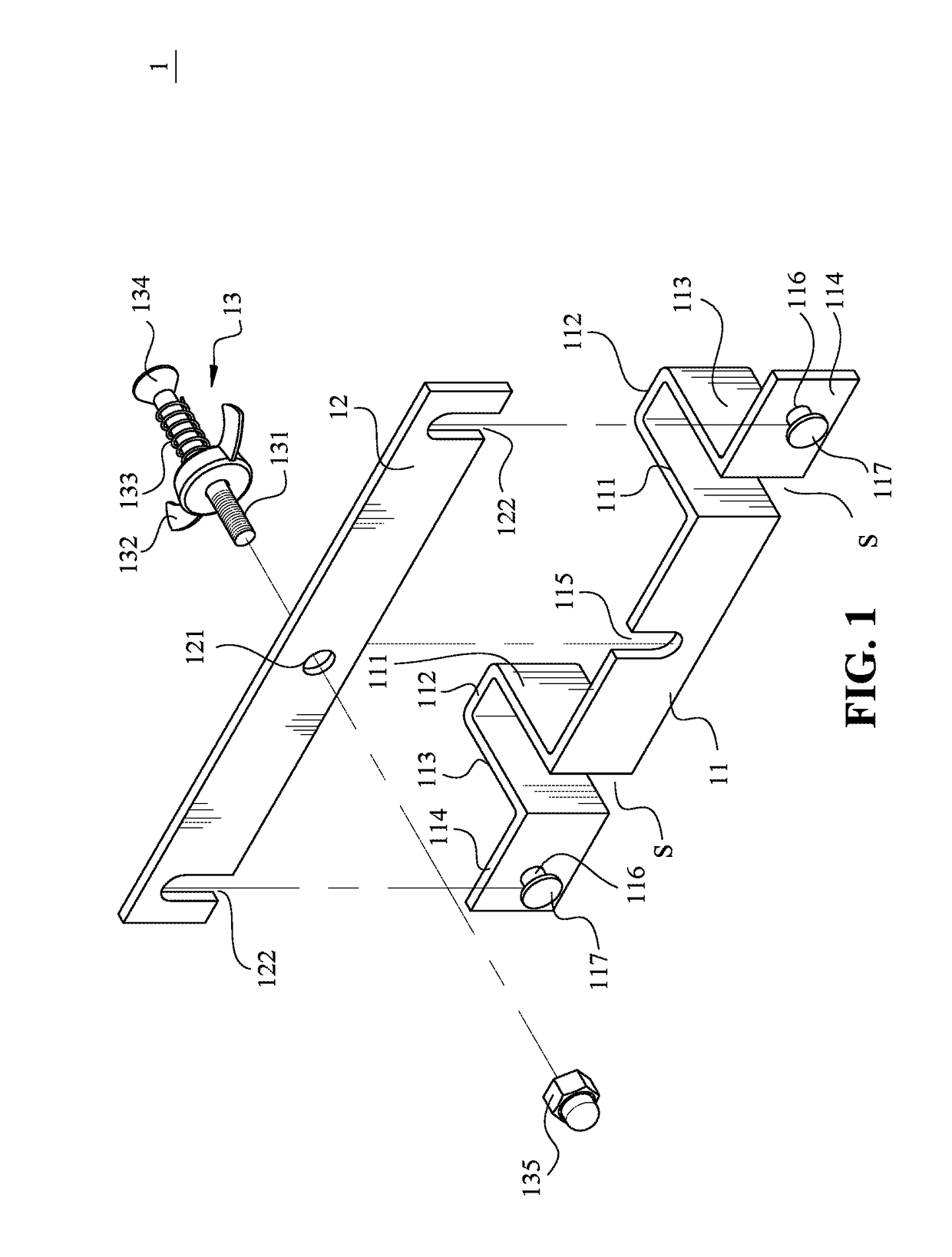
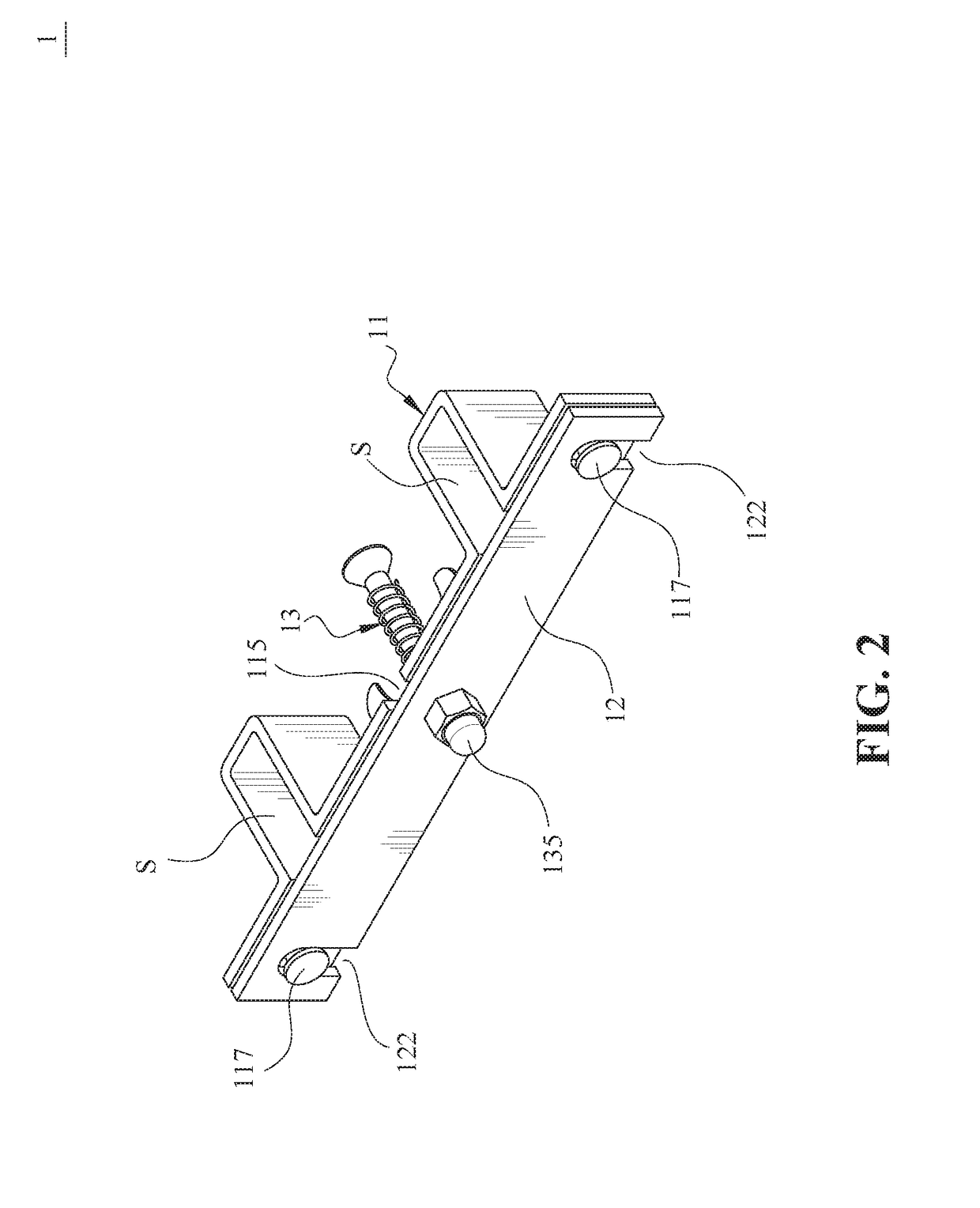
[0027]Referring to FIGS. 1 and 2, wherein FIG. 1 is a perspective and exploded view of a chair fixing device of the present invention; and FIG. 2 is a perspective view of the chair fixing device of the present invention, wherein a sluice gate of the fixing device is shown in a locked position relative to an encircle element. As shown, a chair fixing device of the present invention for fixing two adjacent chairs, includes an encircle element 11, a sluice gate 12 and a locking member 13.

[0028]The encircle element 11 is a flat metal plate with a suitable thickness, and has left and right lateral sides 114 and an intermediate portion that is located between the left and right lateral sid...


PUM


Abstract

A fixing device includes an encircling element having left and right lateral sides and an intermediate portion that is formed with a notch and that is bent to form two limiting apartments at two sides of the notch, each limiting apartment having left and right walls extending integrally and transversely from a longitudinal axis of the encircling element and a middle wall interconnecting the walls that define an opening accessible only from a direction that is the same direction, each of the left and right lateral sides is formed with a retainer stub; a sluice gate having two notches disposed on the retainer stubs for denying access into the apartments; and a locking member extending through a through hole in the sluice gate and the notch in the encircling element for preventing untimely disengagement of the sluice gate from the encircling element.

Description

BACKGROUND OF THE INVENTION1. Field of the Invention[0001]The present invention relates generally to a fixing device, and more particularly to a fixing device for chairs, especially for connecting and fixing an adjacent pairs of chairs or a row of chairs.2. The Prior Arts[0002]In an assembly hall or a baseball stadium, pluralities of foldable chairs or seats are arranged in rows in order to permit seating of audience for watching a game or match. During the chair arrangement, after unfolding each independent chair, the adjacent pairs of chairs are coupled together via a connector or fixing device such that only a relatively small space is left between the adjacent pair of chairs. Under this condition, it may cause discomfort to the seated persons if at least one of them is fat or hefty. To eliminate the above drawback, the chairs should be arranged independently and individually so as to permit appropriate gap between adjacent two chairs, however this may lead to overall unevenness ...

Claims


Application Information

Patent Timeline
IPC IPC(8): A47C15/00A47C1/124A47B87/00F16B2/06F16B2/10A47C7/02A47C7/58A47C31/00A41F1/00
CPCA47C7/58A47B87/007A47C1/124A47C7/02F16B2/065F16B2/10A41F1/00A47C31/00F16B2/12
Inventor LIN, MEI CHUEN
Owner SPEC SEATS TECH
Learn More