

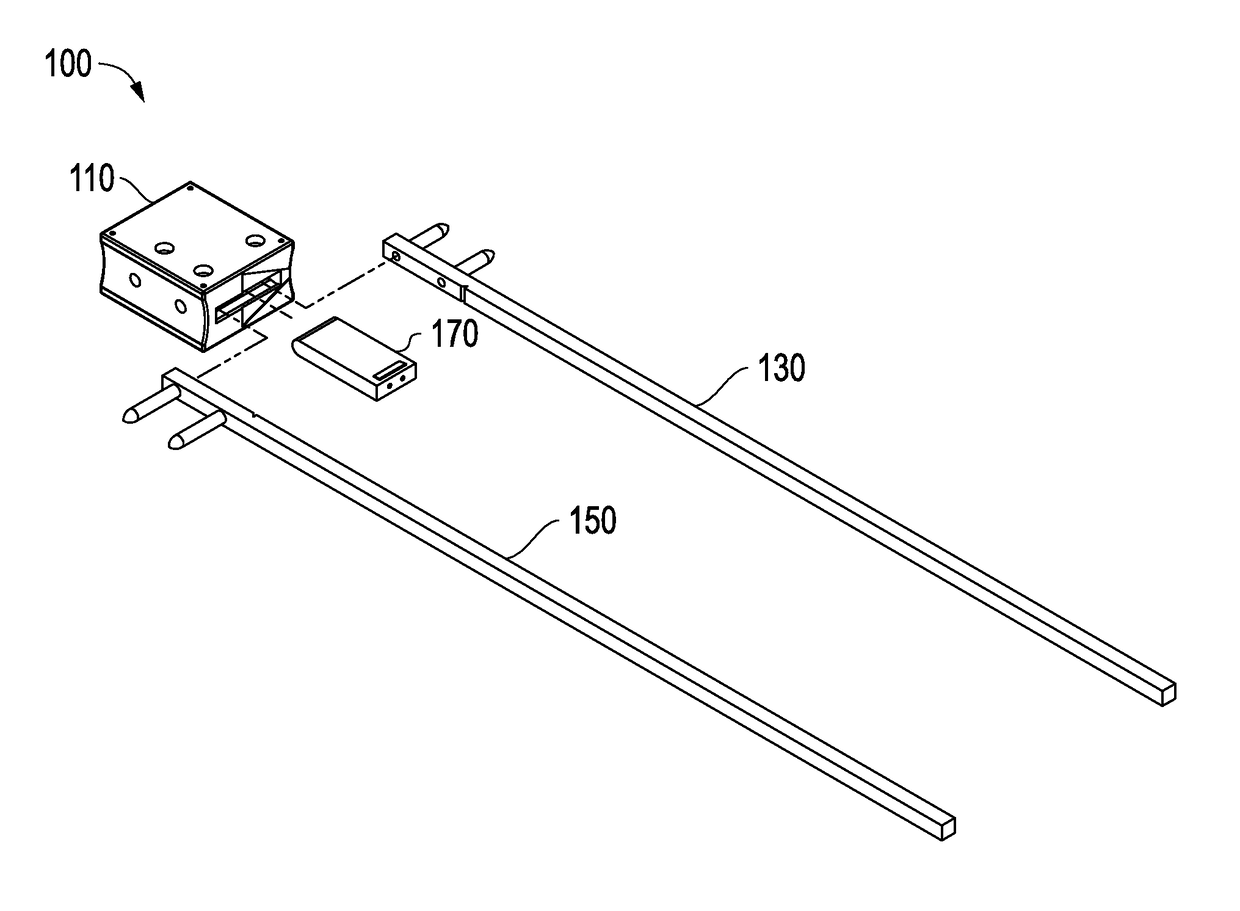
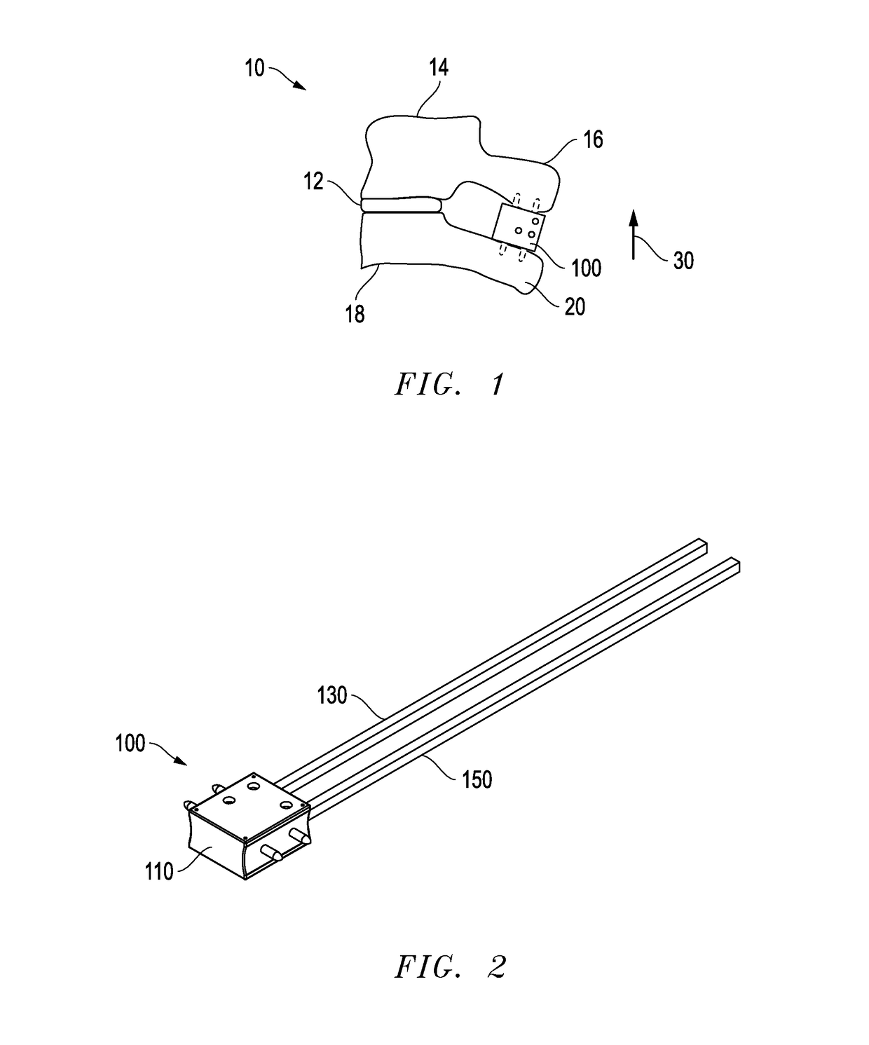
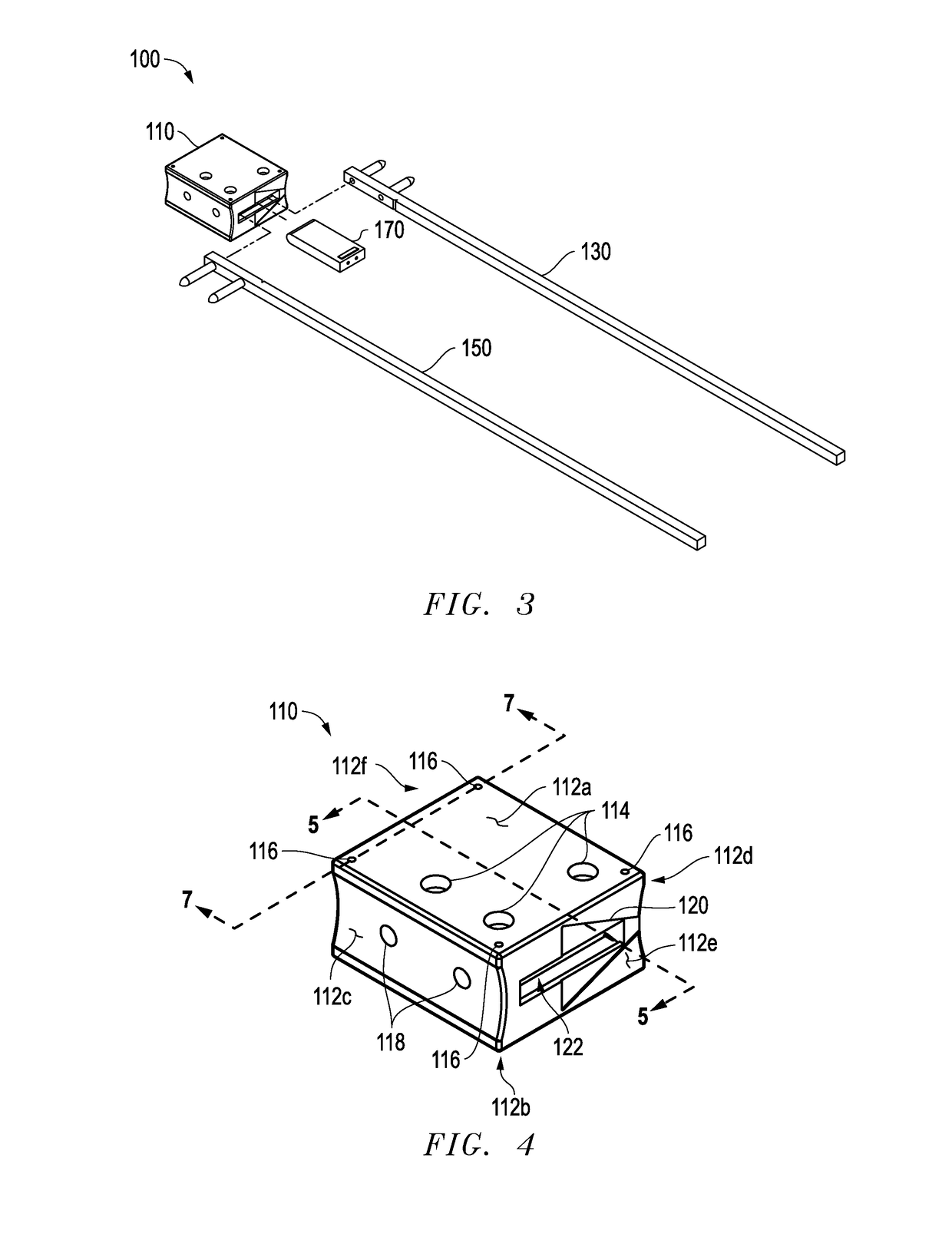
Interlaminar fixation device
a technology of interlaminar fixation and implant body, which is applied in the field of interlaminar fixation device, can solve the problems of high failure rate of device, decrease of spine cross-sectional area, and significant morbidity of patients, and achieve the effect of preventing backing out and facilitating insertion into the implant body
- Summary
- Abstract
- Description
- Claims
- Application Information
AI Technical Summary
Benefits of technology
Problems solved by technology
Method used
Image

Examples
second embodiment
[0119]Method of Implantation Using Second Embodiment
[0120]Referring to FIGS. 78-81, a preferred method 1200 of implanting ILFD 100 using locking plug 900 (instead of 170) in a spine 10 (see FIG. 1) of a patient using implant-sizing tool 200 (discussed above), implant-grasper tool 800, locking-plug inserter tool 1000, bone-punch tool 500, and pin-inserter 600 is described. For clarity, spine 10 is omitted. Method 1200 is substantially the same as described above and shown in FIGS. 36-52, except as described below.
[0121]In method 1200, assembly and placement of implant body 110, fixation-pin assemblies 130 and 150, locking plug 900 as shown in FIG. 78, and preceding steps, are substantially the same as described above and shown in FIGS. 36-44. Next, locking-plug inserter tool 1000 is positioned so that concave seat 1014 engages horn 806 (step 1202). Trigger 1060 is then depressed until inserter tip 1070 addresses grasper opening 920 of locking plug 900 (step 1204) and then fully depre...
PUM
 Abstract
Description
Claims
Application Information