Supercharge Your Innovation With Domain-Expert AI Agents!

Auxiliary circuit for overvoltage protection

a technology of auxiliary circuits and overvoltage protection, applied in emergency protective arrangements, electrical equipment, emergency protection arrangements for limiting excess voltage/current, etc., can solve problems such as electrical overstress damage, gate current may not be sufficient to trigger thyristor, and wiring subject to foreign electromagnetic disturbances

Active Publication Date: 2018-07-17
MITEL NETWORKS INC
View PDF3 Cites 0 Cited by
  • Summary
  • Abstract
  • Description
  • Claims
  • Application Information

AI Technical Summary

Benefits of technology

The patent describes an auxiliary circuit that can protect integrated circuits from overvoltage events. The circuit includes a diode and a transistor to provide current to an overvoltage protection device during a negative-going overvoltage event. The circuit can also include a voltage dropper to dissipate power from the current. The technical effect of the circuit is to ensure that integrated circuits are protected against overvoltage events and can operate safely.

Problems solved by technology

Tip and Ring telephony wiring is subject to foreign electromagnetic disturbances that may be caused by a number of events such as lightning, proximity to other electronic wiring and / or devices (e.g., welding equipment), electrostatic discharge, and the like.
However, if dv / dt is relatively small, as might occur from a negative-going 50-60 Hz AC power line crossing the Tip 130 and / or Ring 140, the gate current may be insufficient to trigger the Thyristor.
In this case the capacitor 180 will continuously charge negatively, causing the rail 160 to exceed a rating of the SLIC 110, resulting in electrical overstress damage.

Method used


Image

  • Auxiliary circuit for overvoltage protection
  • Auxiliary circuit for overvoltage protection
  • Auxiliary circuit for overvoltage protection

Examples


Embodiment Construction

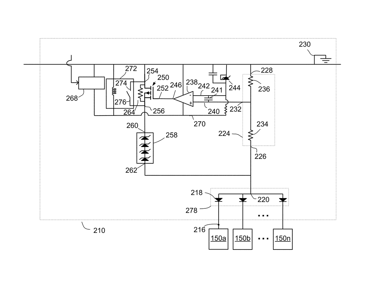
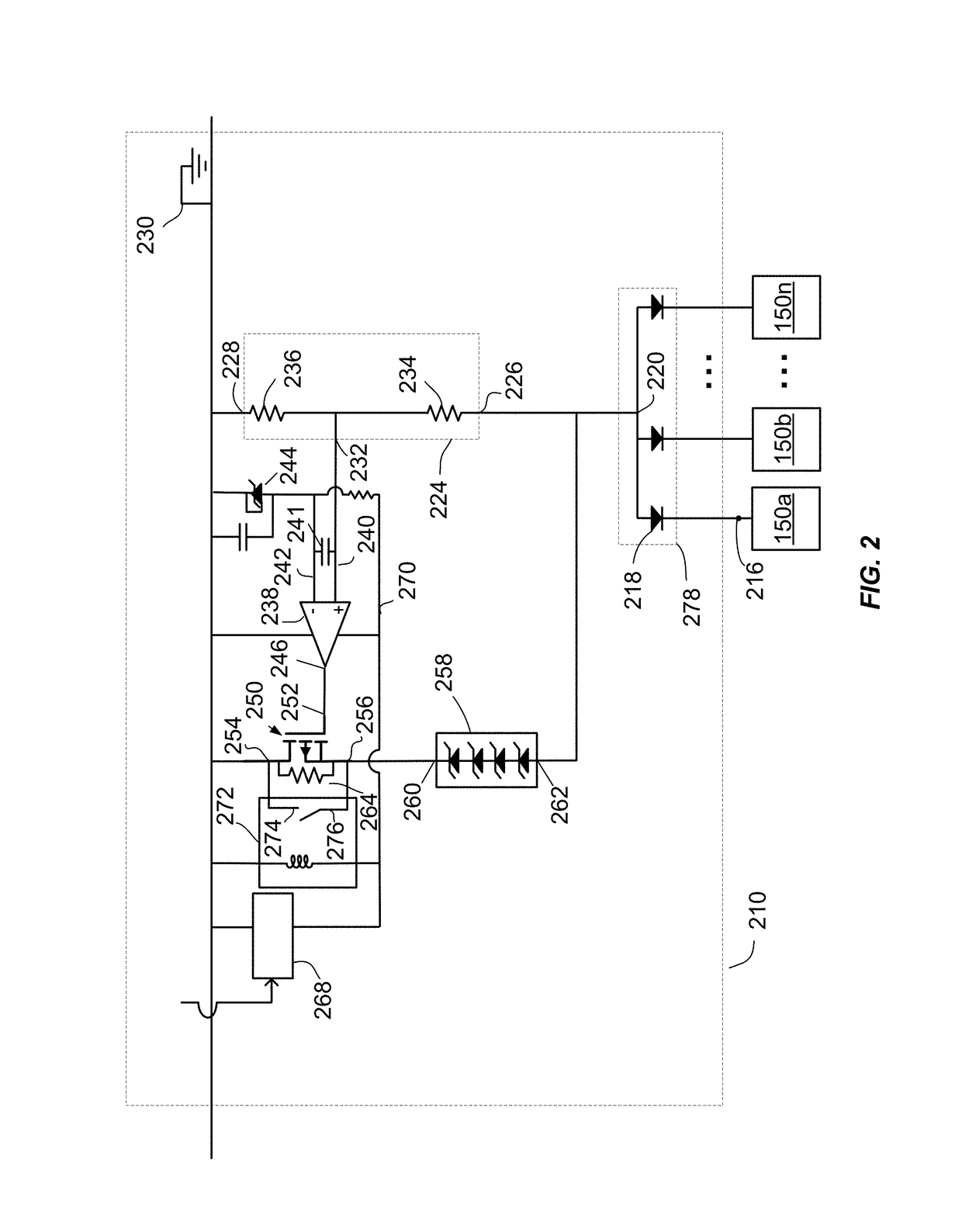
[0032]Embodiments described herein relate generally to auxiliary circuits for overvoltage protection. In some embodiments, the auxiliary circuits may be configured for use with conventional overvoltage protection devices. The auxiliary circuits provide protection against overvoltage events, particularly slow changing overvoltage events, that may not otherwise turn on the overvoltage protection device to clamp the voltage.

[0033]Embodiments in this application are described in relation to telephony systems, and in particular telephony systems using SLICs. These systems operate on a negative voltage framework. The embodiments are not limited to this particular application, however, and may be used with other systems that operate on a positive voltage framework by adjusting voltage ranges and thresholds.

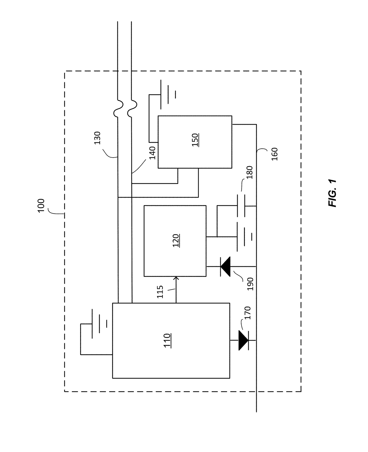
[0034]FIG. 1 is a simplified diagram of an exemplary system 100 with which one or more embodiments of the present invention may be used. The SLIC 110 may be connected to an analog teleph...


PUM


Abstract

An auxiliary circuit for providing current to an external device includes a first switch disposed between a first node and a second node. The first switch is configured to electrically couple the first node to the second node when a first voltage exceeds a first threshold. A comparison circuit has an input coupled to the second node and is configured to compare a second voltage at the input to a second threshold. A second switch has a control terminal coupled to an output of the comparison circuit, a first terminal coupled to a source, and a second terminal for coupling to the external device. The comparison circuit is configured to provide a third voltage at control terminal when the second voltage exceeds the second threshold. The second switch is configured to provide the current from the source to the external device when the third voltage exceeds a threshold of the second switch.

Description

FIELD OF INVENTION[0001]Embodiments described herein relate generally to auxiliary circuits for overvoltage protection. The auxiliary circuits may be used, for example, in conjunction with conventional overvoltage protection devices to provide overvoltage protection to circuits such as telephony subscriber line interface circuits (SLICs).BACKGROUND[0002]In telephony systems, a foreign exchange station (FXS) may use SLICs to provide service to analog telephones. The SLICs are used to perform a number of different tasks such as supplying power to a telephone circuit, detecting telephone status (e.g., on-hook / off-hook), detecting dialing information, sending and receiving voice signals, supporting analog-to-digital and digital-to-analog conversion of voice signals, and other tasks.[0003]Each telephone is connected to a SLIC by two wires that are referred to as Tip and Ring for legacy reasons. The telephony industry uses a negative voltage framework (i.e., a negative operating voltage o...

Claims


Application Information

Patent Timeline
Patent Type & Authority Patents(United States)
IPC IPC(8): H02H3/20H02H1/06H02H9/04
CPCH02H9/04H02H1/06H04M3/18H04M2201/80
Inventor HEY, GEORGE MICHAEL
Owner MITEL NETWORKS INC
Features
  • R&D
  • Intellectual Property
  • Life Sciences
  • Materials
  • Tech Scout
  • Unparalleled Data Quality
  • Higher Quality Content
  • 60% Fewer Hallucinations
Learn More