
Belt conveying device and image forming apparatus having steering control mechanism

a technology of conveying device and conveying device, which is applied in the direction of electrographic process apparatus, instruments, optics, etc., can solve the problems of easy cause of color misalignment, deviation of belt, and inability to achieve uniform transmission, so as to reduce the excessively high moving speed of the belt and reduce the transitional change in the conveying condition of the bel

Active Publication Date: 2018-07-24
CANON KK
View PDF12 Cites 1 Cited by
  • Summary
  • Abstract
  • Description
  • Claims
  • Application Information

AI Technical Summary

Benefits of technology

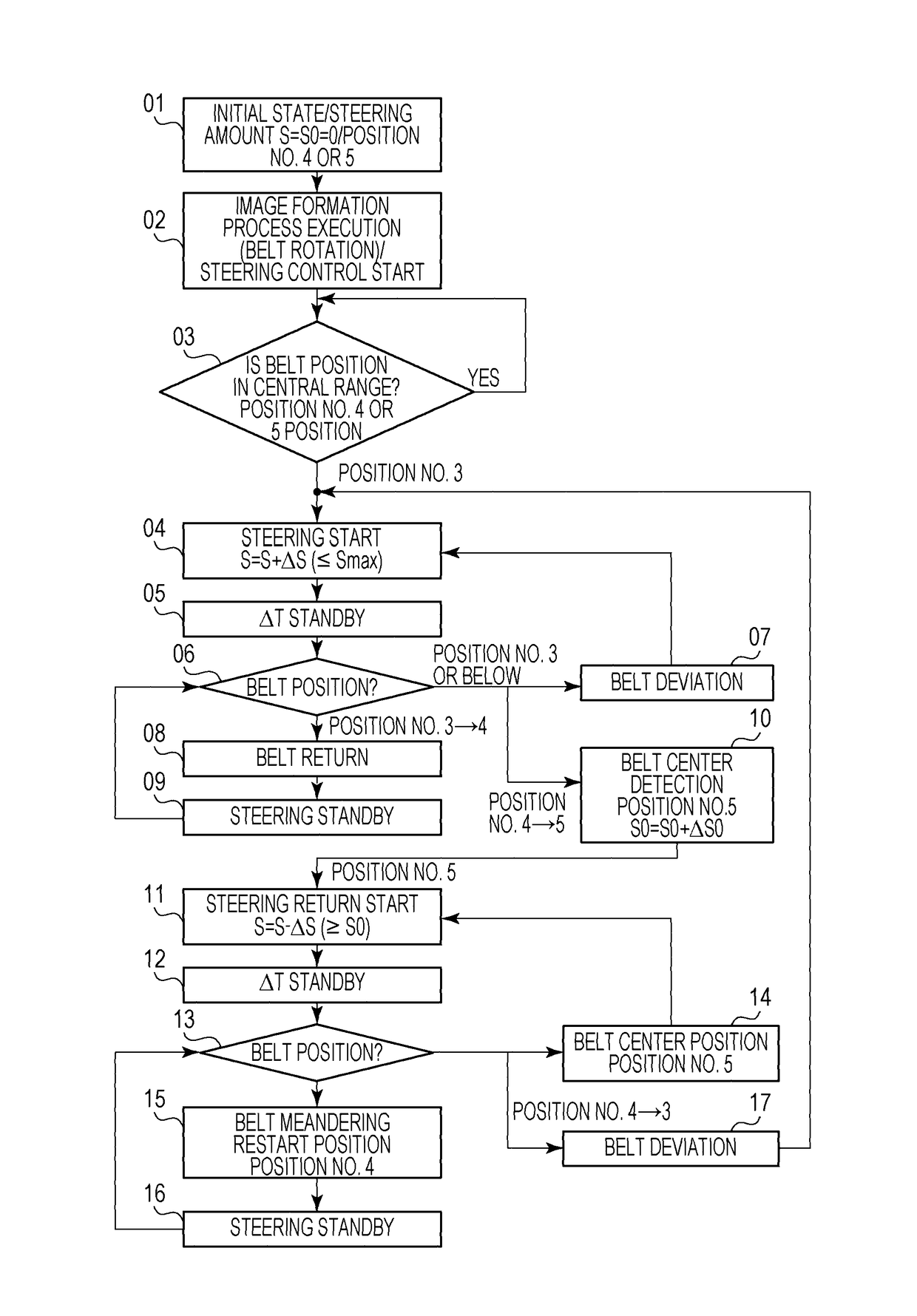
[0011]Aspects of the present invention provide a belt conveying device and an image forming apparatus capable of reducing a transitional change in a conveyance condition of a belt due to tilting of a steering roller and reducing an excessively high moving speed of the belt in a width direction.

Problems solved by technology

A belt trained around a plurality of tension rollers and driven to rotate (i.e., conveyed) generally has a problem of “belt deviation (i.e., meandering)” which is a phenomenon that the belt deviates toward either one end portion in the width direction when driven to rotate.
This is because the change in the conveyance condition of the belt on a surface to which the toner images are transferred from a plurality of image bearing members (i.e., an image transfer surface) causes misalignment in positions at which the toner images of a plurality of colors overlap one another, and causes “color misalignment” which may impair quality of an output image.
If a moving speed of the belt in the width direction to correct the deviation of the belt position in the width direction is high, color misalignment may easily be caused especially in the width direction of the belt.
However, as an operation of a mechanism system which causes the steering roller to be tilted becomes more quasi-static, an influence of friction becomes larger, and the tilting operation may become unstable due to backlash and stick slip of mechanical components.
That is, there is a limit in making the tilting operation itself of the steering roller gentle (i.e., making the tilting speed itself lower).

Method used


Image

  • Belt conveying device and image forming apparatus having steering control mechanism
  • Belt conveying device and image forming apparatus having steering control mechanism
  • Belt conveying device and image forming apparatus having steering control mechanism

Examples


first embodiment

1. Entire Configuration and Operation of Image Forming Apparatus

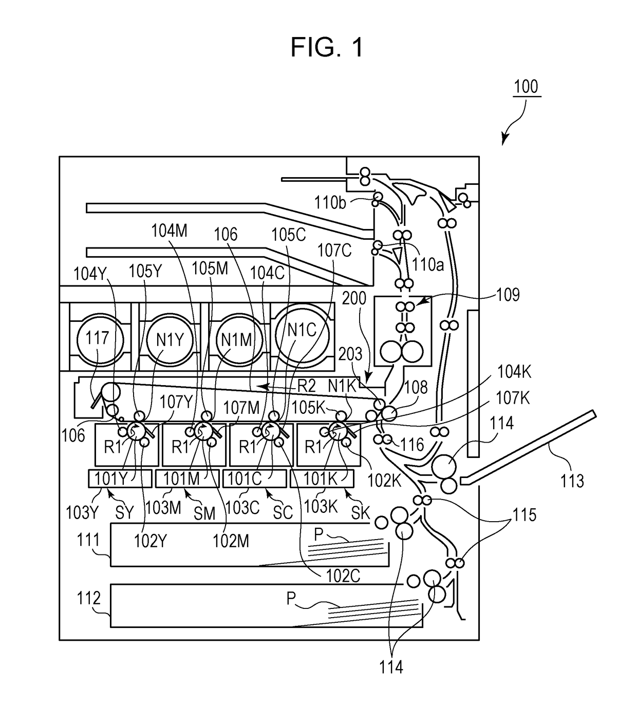
[0034]FIG. 1 is a schematic cross-sectional view of an image forming apparatus according to an embodiment of the present invention. An image forming apparatus 100 of the present embodiment is a tandem color digital printer of an intermediate transfer system capable of forming a color image using an electrophotographic system.

[0035]The image forming apparatus 100 includes a plurality of image forming units (i.e., stations): first, second, third and fourth image forming units SY, SM, SC and SK for forming images of yellow (Y), magenta (M), cyan (C) and black (K), respectively. In the present embodiment, the image forming units SY, SM, SC and SK are substantially the same in basic configuration and operation except for the color of toner used in a developing process. Therefore, unless distinction is required, the image forming units SY, SM, SC and SK will be described collectively as an image forming unit S without attachi...


PUM


Abstract

A belt conveying device is configured such that if belt deviation in which a belt moves in a direction separated from a predetermined position is detected by a belt position detection mechanism, a control unit controls a driving unit to make a steering roller to be tilted intermittently in a direction to correct the belt deviation and, if it is detected by the belt position detection mechanism that a moving direction of the belt has changed to a direction to approach the predetermined position in a suspension period between the intermittent tilting operation, suspends the subsequent tilting of the steering roller.

Description

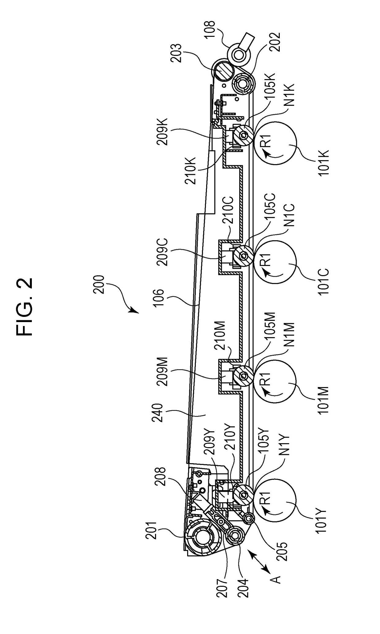
BACKGROUND[0001]Field[0002]Aspects of the present invention generally relate to a belt conveying device used in an image forming apparatus, such as a copier, a printer, and a facsimile machine of an electrophotographic system or an electrostatic recording system, and relates also to an image forming apparatus provided with the belt conveying device.[0003]Description of the Related Art[0004]In an image forming apparatus of an electrophotographic system or an electrostatic recording system, a belt conveying device provided with an endless belt (hereafter, also referred to as a “belt”) trained around a plurality of tension rollers is used. The belt is used as a conveyance member which bears and conveys a toner image, and bears and conveys a recording material on which the toner image is formed. The conveyance member which bears and conveys the toner image may be, for example, a belt-shaped electrophotographic photoconductor (a photoconductor belt), and an intermediate transfer member (...

Claims


Application Information

Patent Timeline
Patent Type & Authority Patents(United States)
IPC IPC(8): G03G15/16
CPCG03G15/1615
Inventor TSUKIJIMA, HISASHI
Owner CANON KK
Learn More