
Flex connection for high altitude balloons

a high-altitude balloon and flex connection technology, applied in the direction of balloon aircraft, etc., can solve the problems of inability to meet the requirements, inability to connect to data, unreliable and/or costly,

Active Publication Date: 2018-07-31
AEROSTAR INT LLC
View PDF12 Cites 6 Cited by
  • Summary
  • Abstract
  • Description
  • Claims
  • Application Information

AI Technical Summary

Benefits of technology

This disclosure is about a high altitude balloon system that includes a balloon envelope, a payload, a cable, and a flex connection on the cable. This flex connection allows the payload to maintain a level position relative to the ground while the balloon envelope tilts. The flex connection has a top, a plurality of discs, and a bottom. The technical effect of this disclosure is that it provides a more stable and secure connection between the payload and the balloon envelope during flight.

Problems solved by technology

However, there are many areas of the world where data connectivity is still unavailable, or if available, is unreliable and / or costly.
When in a tilted condition, rigid connection between the payload and the balloon, however, may lead to failure in the despin mechanism.
Typical joints are unable to meet the requirements of the high altitude balloons and thus may not be sufficient for continued use.
For example, universal joints do not offer the required range of motion, having only 1 degree of motion, and have undesirable inflection points.
They also tend to lack smooth transitions between angles and have a cantilever effect that may result in high stresses and possible breaking.
While double universal joints can bend further than universal joint, double universal joints are still limited in the range of motion and are unable to support large axial loads such as those expected during tilt.
Similarly, typically flex couplings and corrugated tubing such as that used in coolant hoses could be used, but may provide insufficient torque transmission between the payload and envelope and may not handle axial load as typically implemented.
In addition, while a cable inside a flex coupling may be used, but manufacturing techniques presently available are not scalable to the number of balloons needed to support an entire network of balloons.

Method used


Image

  • Flex connection for high altitude balloons
  • Flex connection for high altitude balloons
  • Flex connection for high altitude balloons

Examples


example balloon

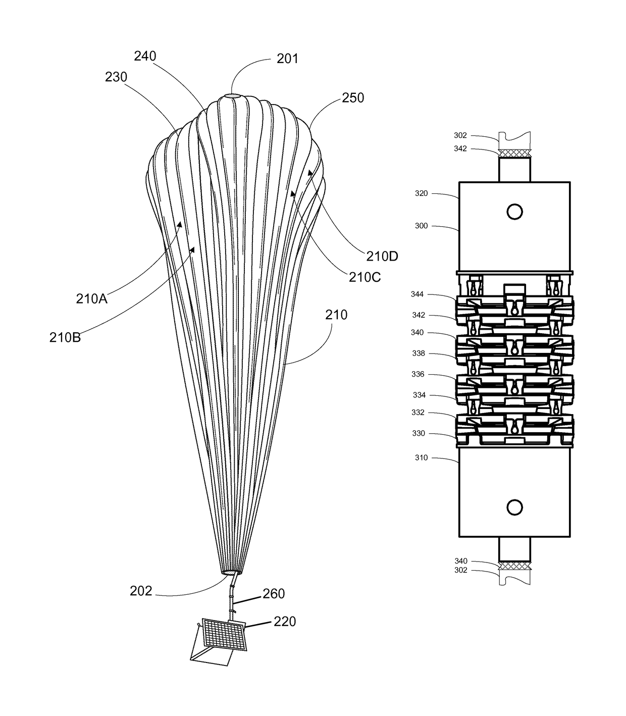
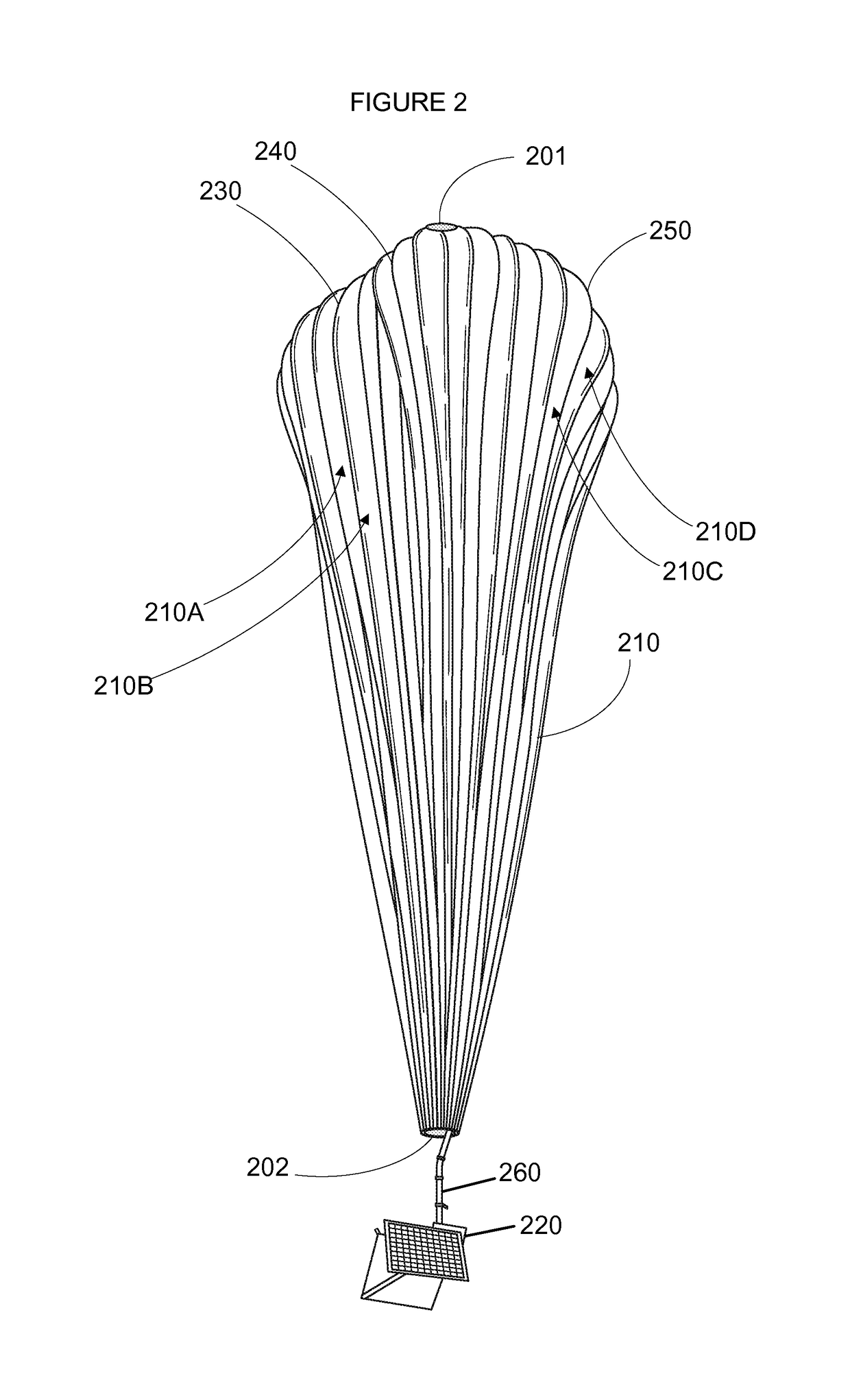
[0034]FIG. 2 is an example balloon 200, which may represent any of the balloons of balloon network 100. As shown, the balloon 200 includes an envelope 210, a payload 220 and a plurality of tendons 230, 240 and 250 attached to the envelope 210.

[0035]The balloon envelope 210 may take various forms. In one instance, the balloon envelope 210 may be constructed from materials such as polyethylene that do not hold much load while the balloon 200 is floating in the air during flight. Additionally, or alternatively, some or all of envelope 210 may be constructed from a highly flexible latex material or rubber material such as chloroprene. Other materials or combinations thereof may also be employed. Further, the shape and size of the envelope 210 may vary depending upon the particular implementation. Additionally, the envelope 210 may be filled with various gases or mixtures thereof, such as helium, hydrogen or any other lighter-than-air gas. The envelope 210 is thus arranged to have an ass...

example assembly

[0040]FIGS. 3 and 4 are example views of a flex connection 300 on a load cable 302. As an example, the load cable 303 may be a 3 / 16 inch steel cable. The flex connection includes a bottom portion 310, a top portion 320, and a plurality of discs 330-344 there between. FIG. 3 depicts the flex connection in a straight or un-flexed orientation, while FIG. 4 shows a flexed orientation of the flex connection as discussed in further detail below. Although not shown, each end of load cable 302 may be mechanically connected to a connection, similar to connection 260 which is mechanically attached to one of the balloon envelope or payload. The connections may therefore mechanically connect the top and bottom portions of the load cable balloon envelope and payload, respectively.

[0041]Each of the bottom and top portions as well as each of the plurality of discs include a respective interior opening. Together, these openings form an open shaft that extends along a length of the flex connection. ...


PUM


Abstract

Aspects of the disclosure provide a flex connection for high altitude balloon applications. During operation flex connection allows a payload of a high-altitude balloon to remain level when an envelope of the balloon is tilted, in order to change the direction of the balloon. As an example, a system may include a balloon envelope, a payload, a cable between the balloon envelope and the payload, and a flex connection on the cable. The flex connection enables the payload to remain level relative to the ground when the balloon is in flight and the balloon envelope is tilted relative to the payload. The flex connection includes a top portion, a plurality of discs, and a bottom portion.

Description

CROSS REFERENCE TO RELATED APPLICATIONS[0001]The present application claims the benefit of the filing date of U.S. Provisional Patent Application No. 62 / 220,607 filed Sep. 18, 2015, the disclosure of which is hereby incorporated herein by reference.BACKGROUND[0002]Computing devices such as personal computers, laptop computers, tablet computers, cellular phones, and countless types of Internet-capable devices are increasingly prevalent in numerous aspects of modem life. As such, the demand for data connectivity via the Internet, cellular data networks, and other such networks, is growing. However, there are many areas of the world where data connectivity is still unavailable, or if available, is unreliable and / or costly. Accordingly, additional network infrastructure is desirable.[0003]Some systems may provide network access via a balloon network operating in the stratosphere. Because of the various forces experienced by these balloons during deployment and operation, there is a bala...

Claims


Application Information

Patent Timeline
Patent Type & Authority Patents(United States)
IPC IPC(8): B64B1/40
CPCB64B1/40Y10T403/32032B64D1/22F16C11/06
Inventor BROOKES, KYLECROMIE, JOHNGRADWOHL, RAYMOND LOUIS
Owner AEROSTAR INT LLC
Learn More